Distance estimation device, distance estimation method, integrated circuit, and computer program

a technology of distance estimation and distance measurement, which is applied in the field of distance estimation devices, distance estimation methods, integrated circuits, and computer programs, can solve the problems of not being able to arrange the phase-difference detection sensors corresponding to all the pixels included in the image, the method is not suitable for distance measurement when the subject is present, and the accuracy of the determined distance is prevented. , the effect of preventing the variation of distance estimation accuracy

Active Publication Date: 2012-06-14
PANASONIC CORP
View PDF5 Cites 65 Cited by
  • Summary
  • Abstract
  • Description
  • Claims
  • Application Information

AI Technical Summary

Benefits of technology

[0078]The present invention is capable of preventing variation in the distance estimation accuracy by calculating distance maps using a plurality of images having different focal positions and synthesizing the distance maps.
[0079]A distance can be determined with a high degree of accuracy in any region (see regions 1RF and 1RN in an image 2I shown in FIG. 2B, for example). Therefore, the accuracy of the determined distance is prevented from varying from region to region, and also variation in the accuracy of distance determination performed on the image regions is prevented. This means that the determination accuracy as can be made uniform.
[0080]A distance can be determined with a high degree of accuracy in any region. Therefore, the accuracy of the determined distance can be increased with reliability.

Problems solved by technology

For this reason, it takes significant time for distance measurement.
In other words, this method is not suitable for distance measurement when the subject is moving.
More specifically, there is a disadvantage that an image in focus needs to be selected from among the captured images for each of the pixels to estimate the distance.
However, it is impossible to arrange the phase-difference detection sensors corresponding to all the pixels included in the image.
Moreover, the size of mechanism to implement this function is inevitably larger as compared with the cases of using the other methods.
The DFD method has a problem that the two images having different focal positions need to be captured with no difference in magnification.
However, it often happens that a normal optical system is not designed in this way.
Moreover, there is another problem that the accuracy in distance estimation can be maintained only in the case of a relatively small amount of blurring.
Since the distance is estimated by performing matching in image processing, it may be hard for the distance estimation accuracy to be relatively high when the power is small, that is, when the amount of blurring is large.
Note that, however, this is not the case for an ideal lens model such as a Gaussian model or a pillbox model.
These methods devising the pupil shape have a problem that, although the distance estimation accuracy increases, the amount of light decreases and the image quality of the all-in-focus image slightly decreases as well.
On this account, this idea has a fundamental problem that the lost information cannot be restored in a subsequent stage of signal processing.
The above-mentioned problem occurs due to this.
However, it is difficult to set a pair of aperture shapes with which the captured images always complement each other's zero points at any distance in any optical system.
Moreover, even on a precondition that a specific optical system is to be used, it is still difficult to set a pair of aperture shapes with which the captured images always complement each other's zero points at any distance.
To be more specific, it is harder to avoid a decrease in the image quality of the restored all-in-focus image than in the case of using the normal optical system.

Method used


Image

  • Distance estimation device, distance estimation method, integrated circuit, and computer program
  • Distance estimation device, distance estimation method, integrated circuit, and computer program
  • Distance estimation device, distance estimation method, integrated circuit, and computer program

Examples


embodiment 1

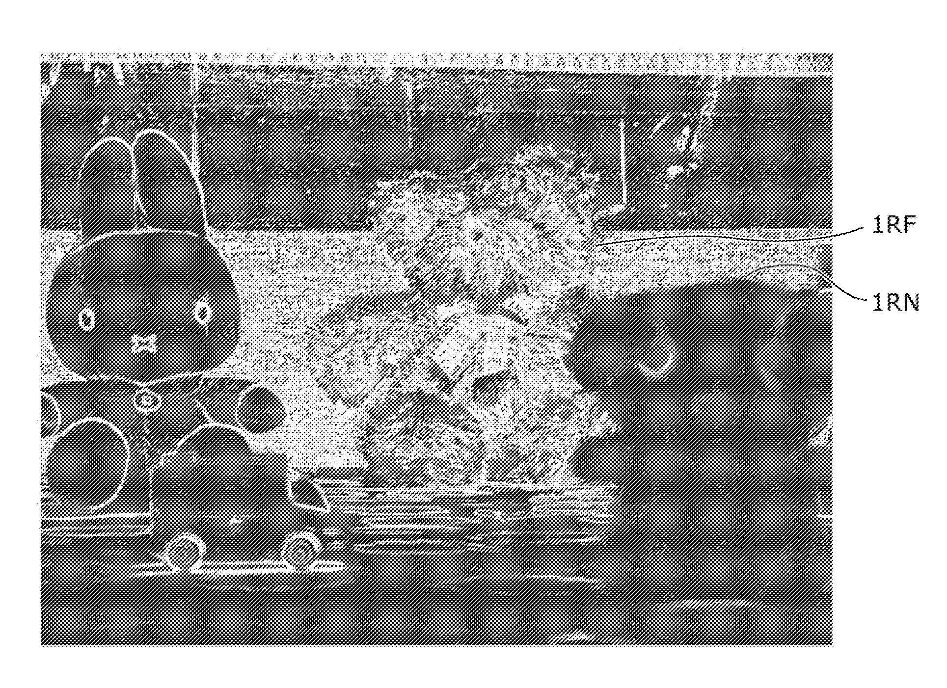
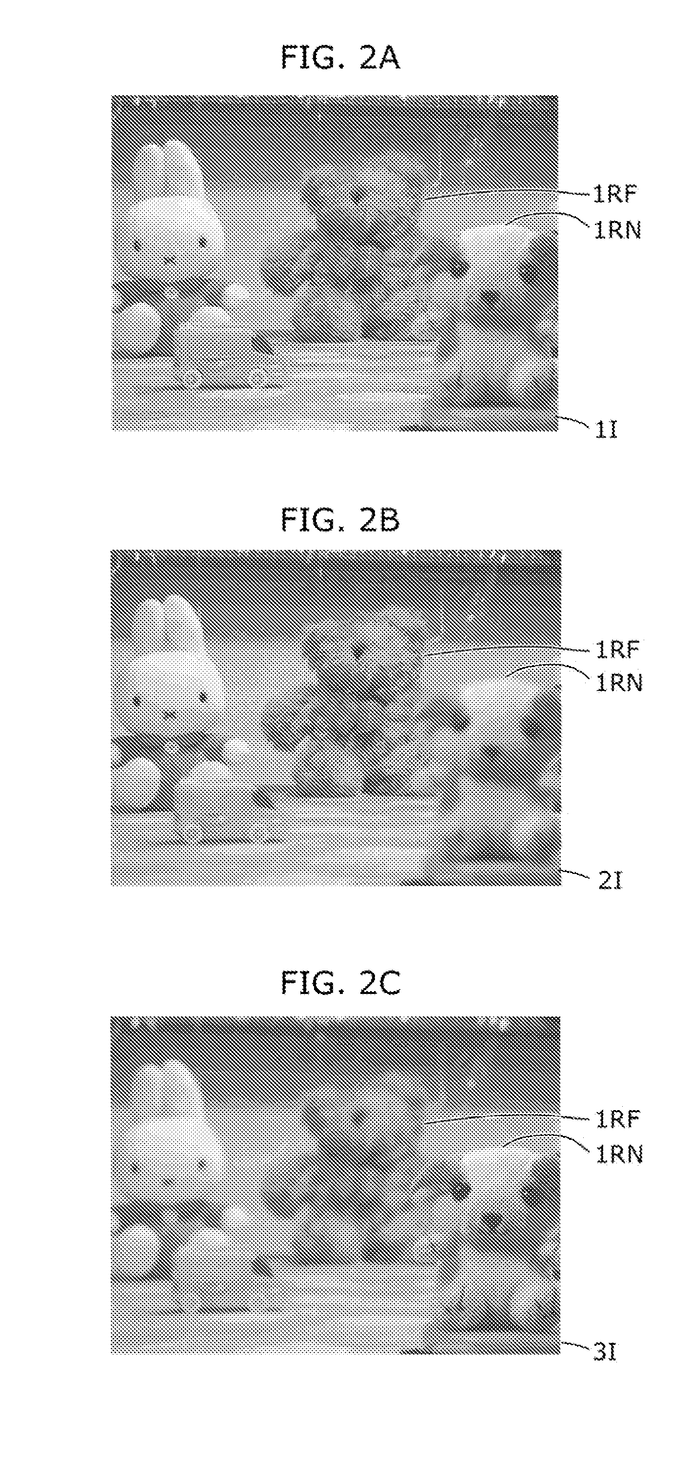
[0111]A distance estimation device and a distance estimation method in Embodiment 1 according to the present invention are described, with reference to FIG. 1, FIGS. 2A to 2C, and FIGS. 3A to 3C. It should be noted that since fundamental components are the same between the distance estimation device and the distance estimation method, only the distance estimation device is described as follows.

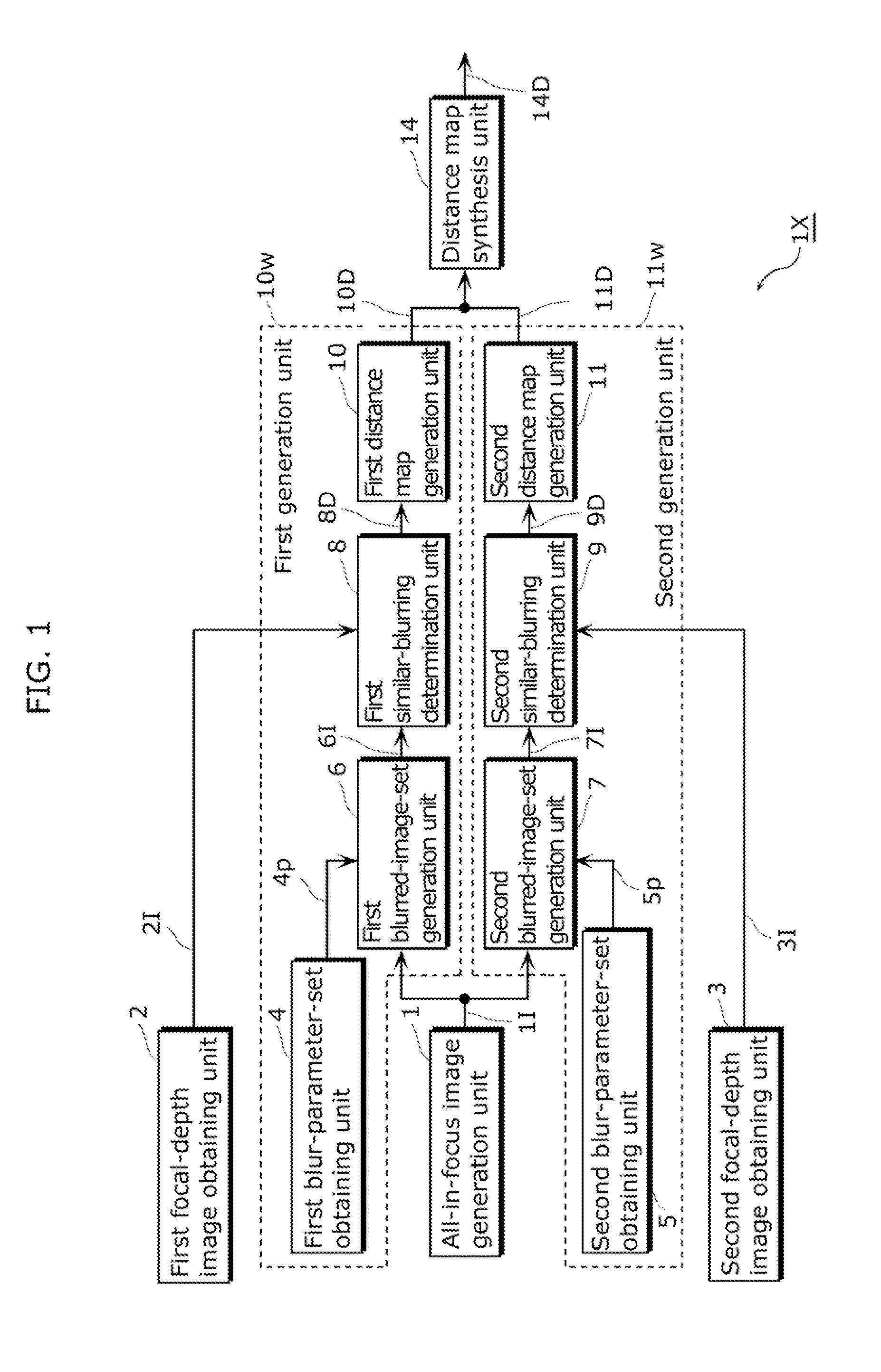
[0112]FIG. 1 is a block diagram showing a configuration of the distance estimation device (the distance estimation device 1x) in Embodiment 1.

[0113]The distance estimation device includes an all-in-focus image generation unit 1, a first focal-depth image obtaining unit 2, a first blur-parameter-set obtaining unit 4, a first blurred-image-set generation unit 6, a first similar-blurring determination unit 8, a first distance map generation unit 10, a second focal-depth image obtaining unit 3, a second blur-parameter-set obtaining unit 5, a second blurred-image-set generation unit 7, a second sim...

embodiment 2

[0147]A distance estimation device and a distance estimation method in Embodiment 2 according to the present invention are described, with reference to FIG. 4, FIGS. 5A to 5C, FIG. 6, and FIG. 7. It should be noted that since fundamental components are the same between the distance estimation device and the distance estimation method, only the distance estimation device is described as follows.

[0148]FIG. 4 shows the distance estimation device (a distance estimation device 1y) in Embodiment 2. This distance estimation device includes a first image characteristic extraction unit 12 and a second image characteristic extraction unit 13 in addition to the configuration of the distance estimation device shown in FIG. 1 in Embodiment 1. Moreover, the distance estimation device in Embodiment 2 includes a distance map synthesis unit 14B (FIG. 4) in place of the distance map synthesis unit 14 (FIG. 1).

[0149]Components assigned with number 1 to 11 are the same as those with these numbers in Em...


PUM


Abstract

A distance estimation device (1x) prevents the variation in distance estimation accuracy that has been a problem in distance estimation performed using an all-in-focus image and an arbitrary-focal-depth image. The distance estimation device can estimate a focal distance of any subject with a high degree of accuracy, and includes: a first generation unit (10w) generating a first distance map indicating a focal depth determined from an all-in-focus image and a first focal-depth image; a second generation unit (11w) generating a second distance map indicating a focal depth determined from the all-in-focus image and a second focal-depth image; and a distance map synthesis unit (14) synthesizing the generated first distance map and the generated second distance map to generate a synthetic distance map.

Description

TECHNICAL FIELD[0001]The present invention relates to a device and a method for estimating a distance to each subject included in an image obtained in moving image capture or continuous still image capture.BACKGROUND ART[0002]In general, a distance estimation method based on a sensing technology is roughly divided into the following two types.[0003]One is an active sensing method. Examples of the active sensing method include a time-of-flight method using a laser or ultrasound, a confocal method commonly used for a microscope or the like, and an illumination stereo method using plural light sources.[0004]The other is a passive sensing method. Examples of the passive sensing method include: a method whereby stereo images are captured and a distance is estimated from a difference between positions of a subject included in the captured images; and a focusing method using a difference in lens focal point based on only one captured image.[0005]The focusing method is a technique used main...

Claims


Application Information

Patent Timeline
Patent Type & Authority Applications(United States)
IPC IPC(8): G06K9/00
CPCG01C3/06G01C3/32G06T7/0069H04N5/23212G02B7/38G06T7/571H04N23/673H04N23/676
Inventor KAWAMURA, TAKASHILASANG, PONGSAK
Owner PANASONIC CORP
Why Eureka
Try Eureka