
Alkali Metal Deposition System

a metal deposition system and alkali metal technology, applied in the field of alkali metal deposition system, can solve the problems of low throughput of prior art alkali and alkali earth metal deposition system, lack of ease of scalability for high throughput, and large substrate, etc., to achieve large surface area, high deposition rate, and large width

Inactive Publication Date: 2012-06-21
APPLIED MATERIALS INC
View PDF7 Cites 8 Cited by
  • Summary
  • Abstract
  • Description
  • Claims
  • Application Information

AI Technical Summary

Benefits of technology

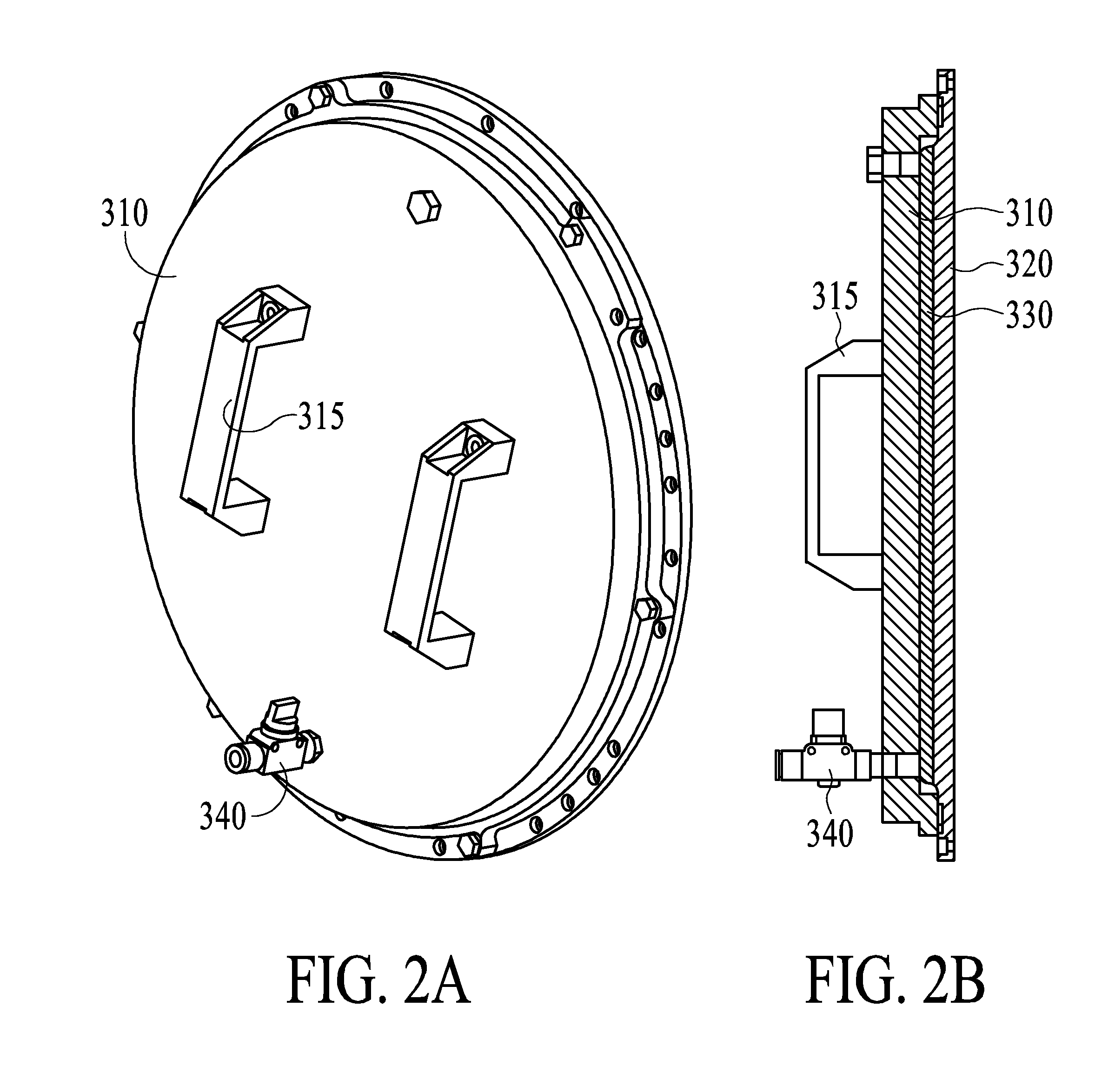
[0006]According to further aspects of the invention, a method of sputter depositing alkali and alkaline earth metals on a substrate may comprise: igniting a plasma between the substrate and a sputter target within a vacuum chamber, wherein the plasma includes noble gas species and the sputter target comprises target material attached to a backing plate including cooling channels; adding energy to the plasma by multiple power sources, wherein the multiple power sources include a first power source for controlling target material self bias, and a second power source for controlling ion density in the plasma; sputtering target material from the sputter target and depositing the sputtered target material on the substrate, wherein the sputtering is by noble gas species from the plasma and wherein the noble gas species include ions with an atomic weight less than the atomic weight of the target material; and during the sputtering, cooling the sputter target by pumping coolant through the cooling channels in the backing plate. Furthermore, the sputter target may be provided with a cover over the target material, the cover being sealed to the sputter target for protection of the target material from ambient gases, the method including installing the sputter target with the cover in the vacuum chamber and removing the cover from the sputter target in the vacuum chamber. The removal of the cover may be either manual or automated, and when automated may be done under vacuum. The adding energy may include one or more of adding RF-DC, pulsed DC-RF, pulsed DC-HF and / or other dual frequency power sources.

Problems solved by technology

Prior art alkali and alkaline earth metal deposition systems are known to have low throughput and lack ease of scalability for high throughput and large substrates.

Method used


Image

  • Alkali Metal Deposition System
  • Alkali Metal Deposition System
  • Alkali Metal Deposition System

Examples


Embodiment Construction

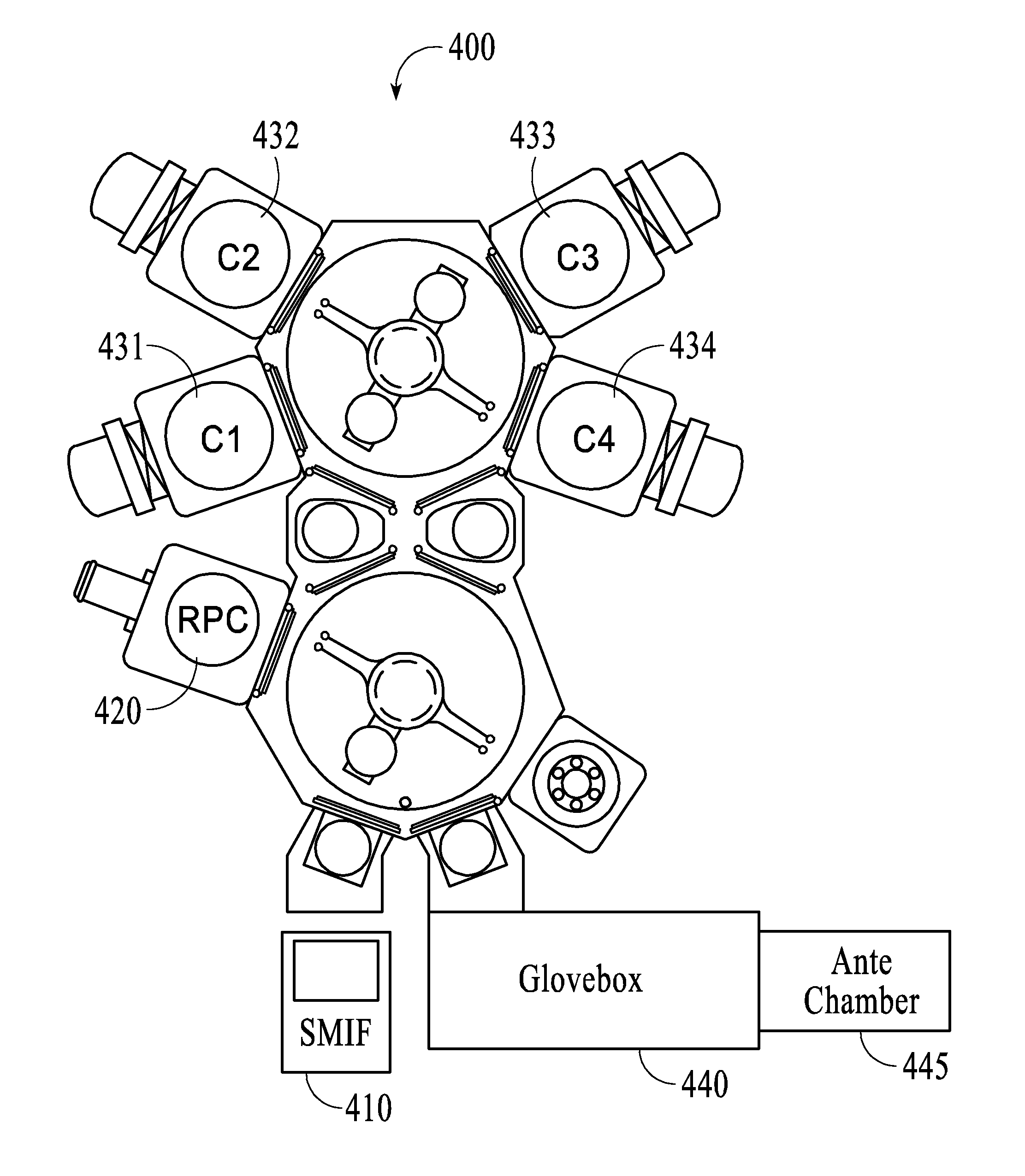
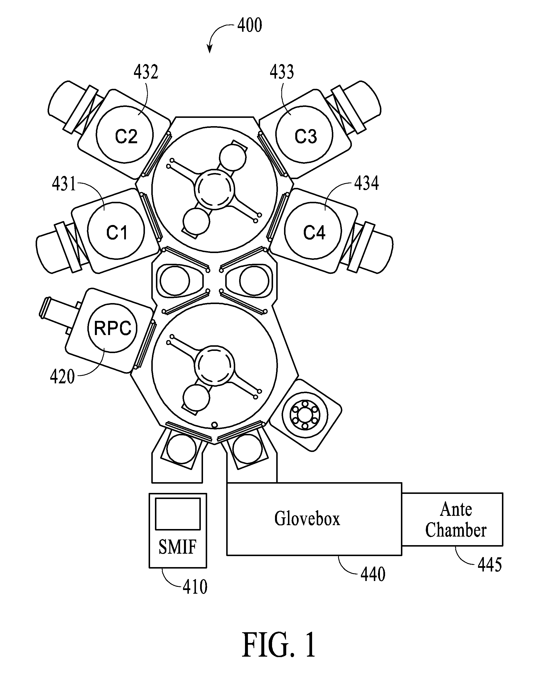
[0017]Embodiments of the present invention will now be described in detail with reference to the drawings, which are provided as illustrative examples of the invention so as to enable those skilled in the art to practice the invention. Notably, the figures and examples below are not meant to limit the scope of the present invention to a single embodiment, but other embodiments are possible by way of interchange of some or all of the described or illustrated elements. Moreover, where certain elements of the present invention can be partially or fully implemented using known components, only those portions of such known components that are necessary for an understanding of the present invention will be described, and detailed descriptions of other portions of such known components will be omitted so as not to obscure the invention. In the present specification, an embodiment showing a singular component should not be considered limiting; rather, the invention is intended to encompass ...


PUM

PropertyMeasurementUnit
temperatureaaaaaaaaaa
sizesaaaaaaaaaa
densityaaaaaaaaaa

Abstract

A deposition system for alkali and alkaline earth metals may include a metal sputter target including cooling channels, a substrate holder configured to hold a substrate facing and parallel to the metal sputter target, and multiple power sources configured to apply energy to a plasma ignited between the substrate and the metal sputter target. The target may have a cover configured to fit over the target material, the cover may include a handle for automated removal and replacement of the cover within the deposition system, and a valve for providing access to the volume between the target material and the cover for pumping, purging or pressurizing the gas within the volume. Sputter gas may include noble gas with an atomic weight less than that of the metal target.

Description

CROSS-REFERENCE TO RELATED APPLICATIONS[0001]This application claims the benefit of U.S. Provisional Application Ser. No. 61 / 417,108 filed Nov. 24, 2010, incorporated by reference in its entirety herein.FIELD OF THE INVENTION[0002]The present invention relates generally to deposition systems for alkali and alkaline earth metals, and more particularly to high throughput deposition systems.BACKGROUND OF THE INVENTION[0003]Prior art alkali and alkaline earth metal deposition systems are known to have low throughput and lack ease of scalability for high throughput and large substrates. There is a need for alkali and alkaline earth metal deposition sources and systems that (1) can be adopted to different substrate formats, including circular, rectangular, etc., (2) may be scaled to accommodate any size of substrate and (3) allow for high throughput deposition—allowing for cost competitive manufacturing of devices such as thin film batteries and electrochromic windows.SUMMARY OF THE INVEN...

Claims


Application Information

Patent Timeline
Patent Type & Authority Applications(United States)
IPC IPC(8): C23C14/34
CPCC23C14/3407H01J37/3426H01J37/34C23C14/564
Inventor KWAK, BYUNG SUNGBANGERT, STEFANKOENIG, MICHAELRIES, FLORIANHOFMANN, RALF
Owner APPLIED MATERIALS INC
Learn More