
Integrated antenna system for imaging microsatellites

Active Publication Date: 2012-06-21
PLANET LABS PBC
View PDF2 Cites 28 Cited by
  • Summary
  • Abstract
  • Description
  • Claims
  • Application Information

AI Technical Summary

Benefits of technology

[0007]Certain challenges are presented when designing microsatellites such as incorporating the desired structure and electronics into a relatively small form factor, maximizing the efficiency of the included components given volume and mass constraints, and providing sufficient communication systems to relay information to and from ground-based systems. Imaging microsatellites, for example, utilize much of the volume of the satellite for the imaging system, reducing the available space for other components, such as antennas for communication. In addition, imaging microsatellites can produce relatively large amounts of information making it desirable to incorporate a communication system capable of a relatively high data transmission rate, consequently making larger antenna systems more desirable.
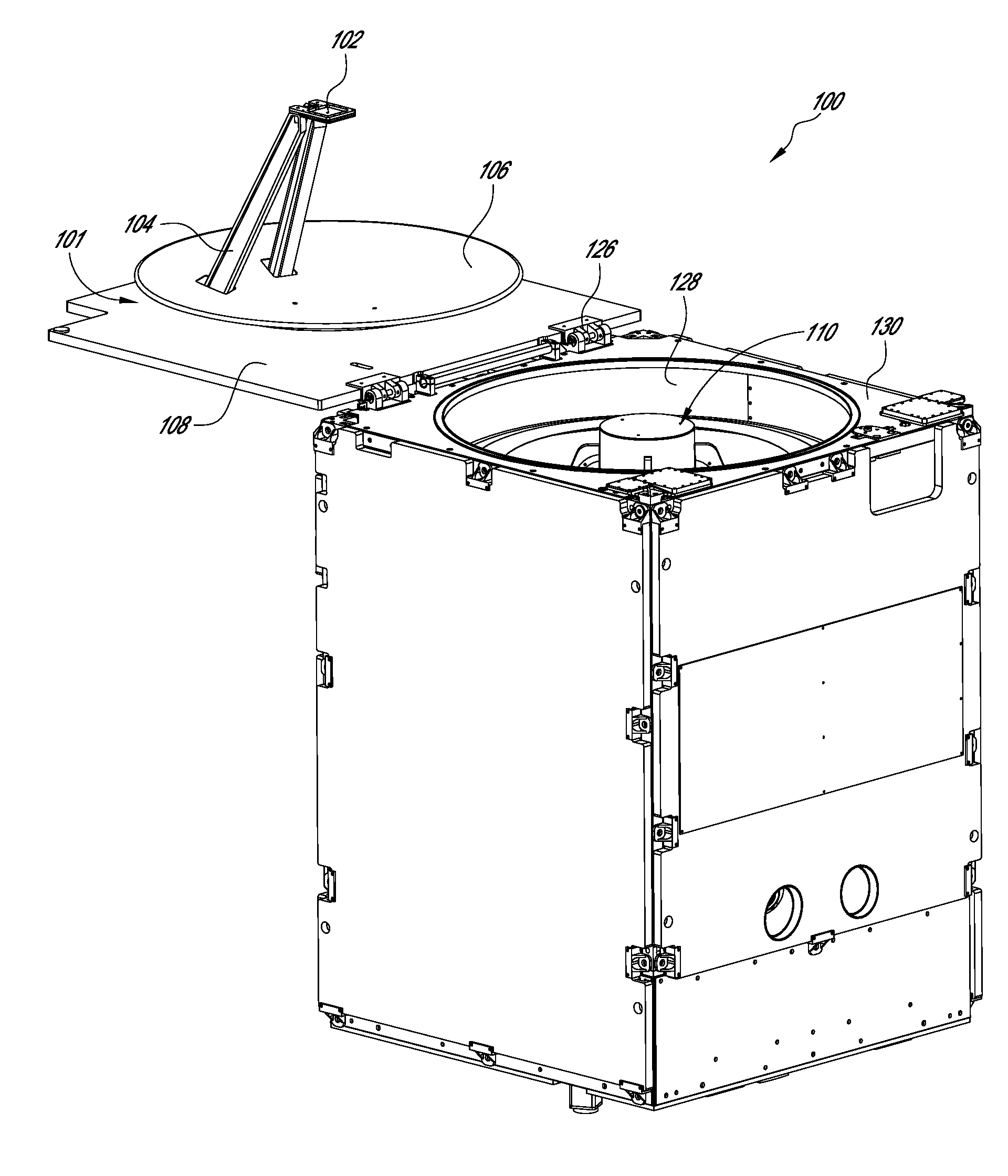
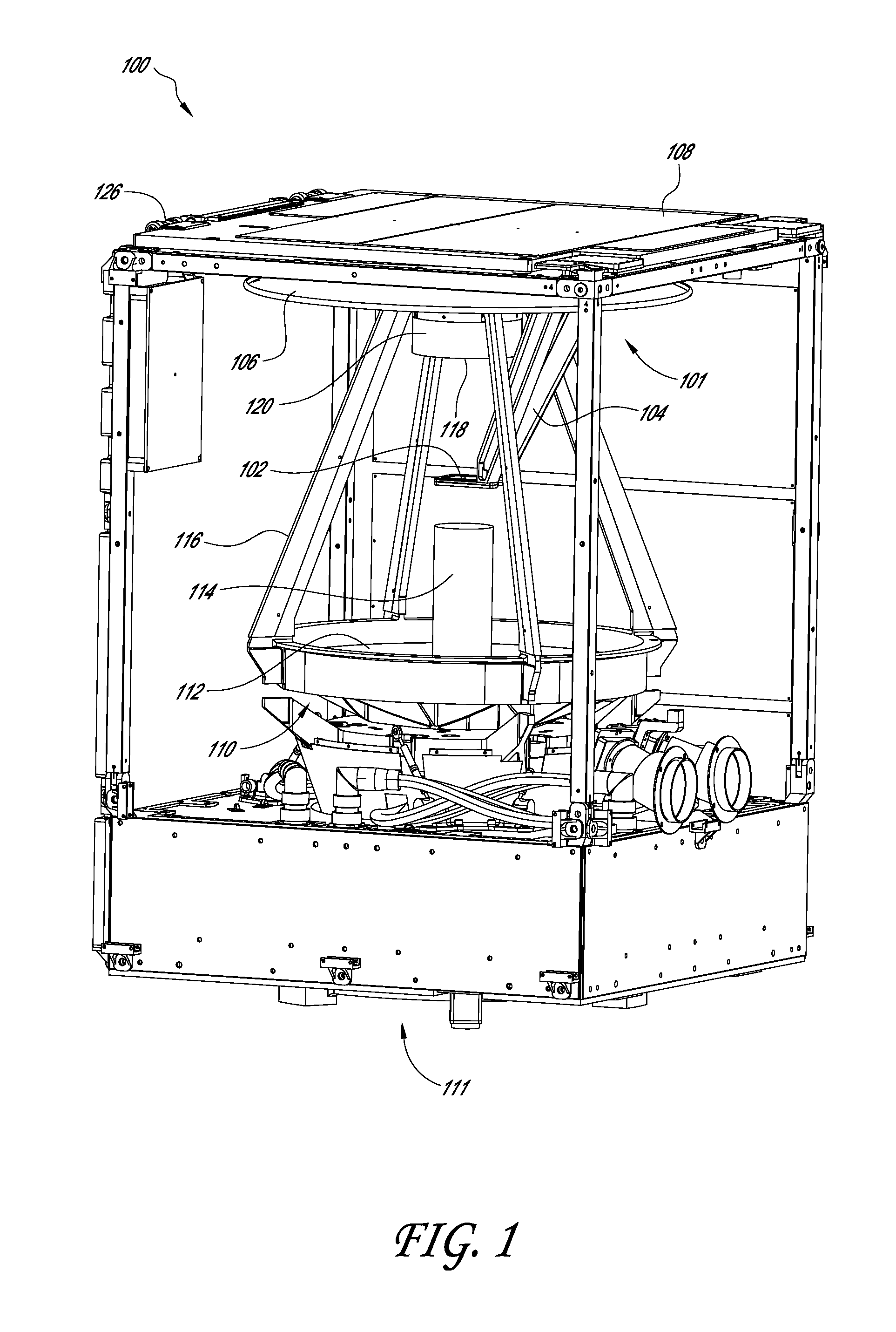
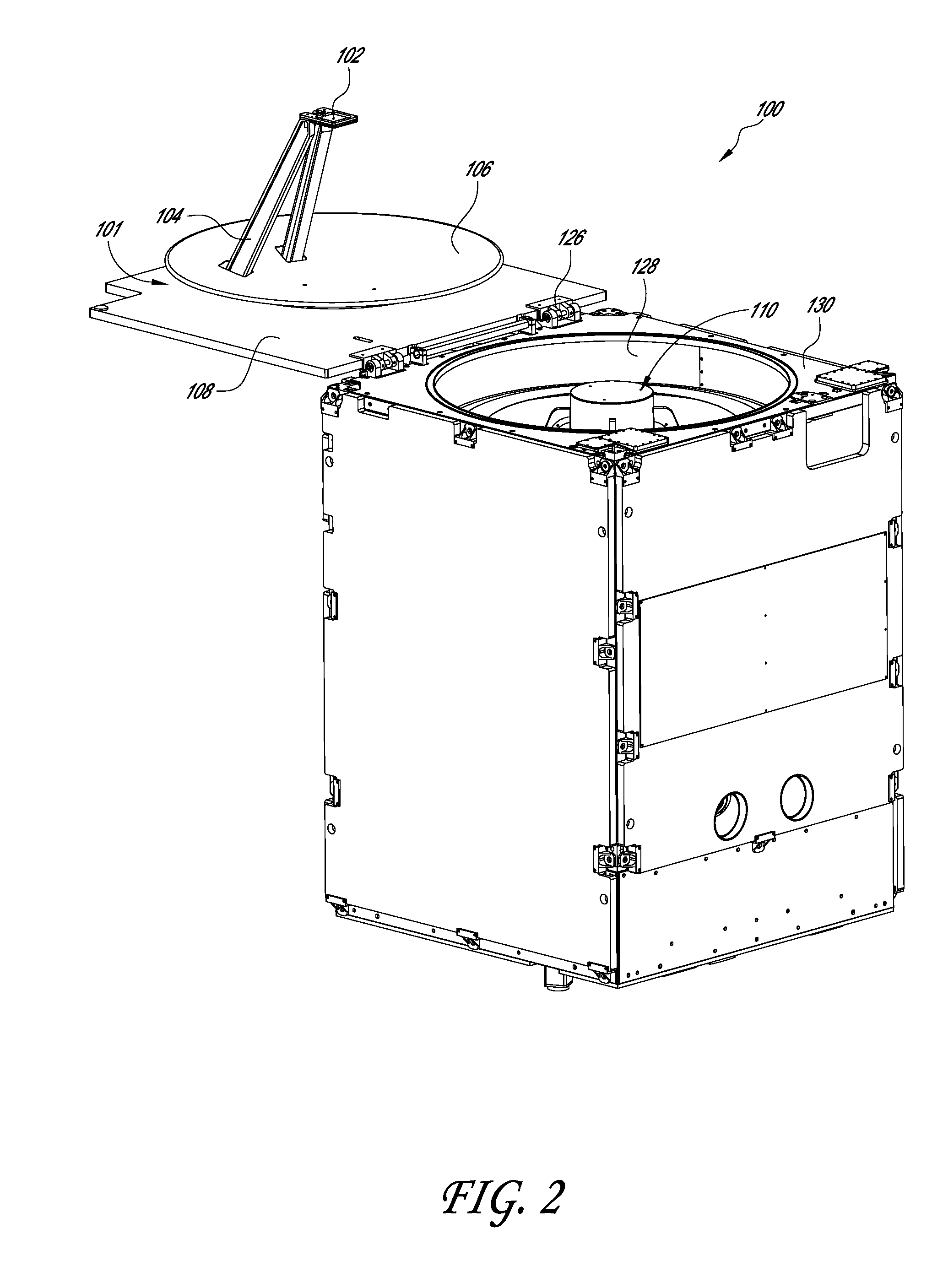
[0008]Microsatellites can be advantageous where satellite capabilities are desirable but the cost to manufacture and launch a traditional, large satellite renders the possibility impracticable or unworkable. Microsatellites are smaller and weigh less than traditional, large satellites and therefore are generally cheaper to manufacture and put into orbit. However, challenges arise when reducing the size of components and systems to fit into a microsatellite. For instance, large satellites may include large communications antennas making high data transmission rates possible. Microsatellites, on the other hand, are limited in the size of antenna that may be included, possibly reducing the data transmission rate available. The gain of the antenna may also be affected by the size of the antenna, affecting the link margin and size of ground communication systems. The gain of the antenna may also be affected by the frequency band of communication with the ground or other satellites. Imaging microsatellites also incorporate imaging systems, reducing the space available for antenna systems. Certain antenna systems may satisfy space and weight concerns yet create additional costs and introduce undesirable complexity into the system. In imaging microsatellites, the imaging system generally has a desired configuration which limits the configuration of other systems and components within the satellite. For example, it may be desirable that the imaging system have a field of view unobstructed by other components when the satellite is deployed. The antenna configuration, then, can be advantageously configured to fit within the body of the microsatellite without disturbing the imaging system configuration. In some embodiments, an imaging microsatellite can be configured to house both an antenna system and an imaging system, communicate with a data rate sufficient to transmit image and video data to a ground-based communication system, reduce system complexity, reduce manufacture costs, optimize the antenna system given the size and / or mass constraints, and / or increase the packing efficiency of both antenna and imaging system.
[0019]The method can include adjusting properties of the antenna system such that the reflector matches a radiation pattern of the antenna feed and a desired antenna gain or data transmission rate is achieved.

Problems solved by technology

Certain challenges are presented when designing microsatellites such as incorporating the desired structure and electronics into a relatively small form factor, maximizing the efficiency of the included components given volume and mass constraints, and providing sufficient communication systems to relay information to and from ground-based systems.
Imaging microsatellites, for example, utilize much of the volume of the satellite for the imaging system, reducing the available space for other components, such as antennas for communication.
Microsatellites can be advantageous where satellite capabilities are desirable but the cost to manufacture and launch a traditional, large satellite renders the possibility impracticable or unworkable.
However, challenges arise when reducing the size of components and systems to fit into a microsatellite.
Microsatellites, on the other hand, are limited in the size of antenna that may be included, possibly reducing the data transmission rate available.
The gain of the antenna may also be affected by the size of the antenna, affecting the link margin and size of ground communication systems.
Imaging microsatellites also incorporate imaging systems, reducing the space available for antenna systems.
Certain antenna systems may satisfy space and weight concerns yet create additional costs and introduce undesirable complexity into the system.

Method used


Image

  • Integrated antenna system for imaging microsatellites
  • Integrated antenna system for imaging microsatellites
  • Integrated antenna system for imaging microsatellites

Examples


example method

of Designing an Imaging Microsatellite

[0068]FIG. 6 is a flow diagram representing an example of a method 300 of designing an imaging microsatellite with an integrated reflector antenna system. In operational block 302 configuration parameters of a microsatellite can be obtained. The microsatellite can be configured to conform to the ESPA envelope, or other launch vehicle standards. The configuration parameters can include the design, layout, dimensions, and configuration of the microsatellite including the available interior cavity space and opening through which an imaging system can view the Earth. The configuration parameters can also include the design, layout, dimensions, and configuration of the imaging system disposed within the interior cavity of the microsatellite. For example, the imaging system may include a telescope. The imaging system configuration parameters can include information about the size and configuration of the telescope, its primary and secondary (or other)...


PUM


Abstract

Examples of imaging microsatellites are described that have an imaging system and antenna system disposed within the microsatellite body when the microsatellite is in a non-deployed state. The properties of the antenna system can be adjusted such that the antenna system does not impact, contact, or displace the imaging system when the microsatellite is in the non-deployed state. The properties of the antenna system can be adjusted such that the antenna system does not contact or impact the body of the microsatellite or any other structure when the microsatellite transitions to a deployed state. The antenna system can be configured to achieve a desired gain and / or data transmission rate by adjusting properties of the antenna system based on the radiation pattern of an antenna feed and geometric constraints imposed by the imaging system. Examples of methods for designing such imaging microsatellites are provided.

Description

CROSS-REFERENCE TO RELATED APPLICATIONS[0001]This application claims the benefit of priority under 35 U.S.C. §119(e) of U.S. Provisional Patent Application 61 / 423,473, filed Dec. 15, 2010, entitled “INTEGRATED REFLECTOR ANTENNA AND OPTICAL SEAL FOR MICRO IMAGING SATELLITES,” the disclosure of which is hereby incorporated by reference in its entirety.BACKGROUND[0002]1. Field[0003]The disclosure generally relates to microsatellites, and more particularly, to antenna systems and imaging systems for microsatellites.[0004]2. Description of the Related Art[0005]Microsatellites are satellites that are smaller than traditional satellites. Due to their smaller size, microsatellites generally cost less to build and deploy into orbit above the Earth. As a result, microsatellites present opportunities for educational institutions, governments, and commercial entities to launch and deploy microsatellites for a variety of purposes with fewer costs compared to traditional, large satellites. Micros...

Claims


Application Information

Patent Timeline
IPC IPC(8): H04N7/18G06F17/50
CPCB64G1/1021H01Q1/08H01Q1/288H01Q19/10H04N7/18B64G1/66H04B7/18515H04N7/005B64G1/222
Inventor MIRANDA, HENRIQUE DO CARMO
Owner PLANET LABS PBC
Learn More