

Solder Paste, Joining Method Using the Same and Joined Structure
a technology of joining method and solvent paste, which is applied in the direction of solventing apparatus, manufacturing tools, transportation and packaging, etc., can solve the problems of low reliability, unusable products to be joined, and solvent paste in which sn remains may suffer a considerable reduction in bonding strength, etc., and achieve high melting point, short time, and good diffusibility in the soldering step
- Summary
- Abstract
- Description
- Claims
- Application Information
AI Technical Summary
Benefits of technology
Problems solved by technology
Method used
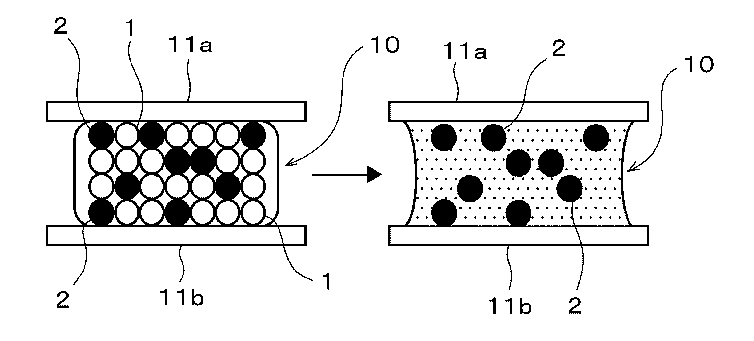
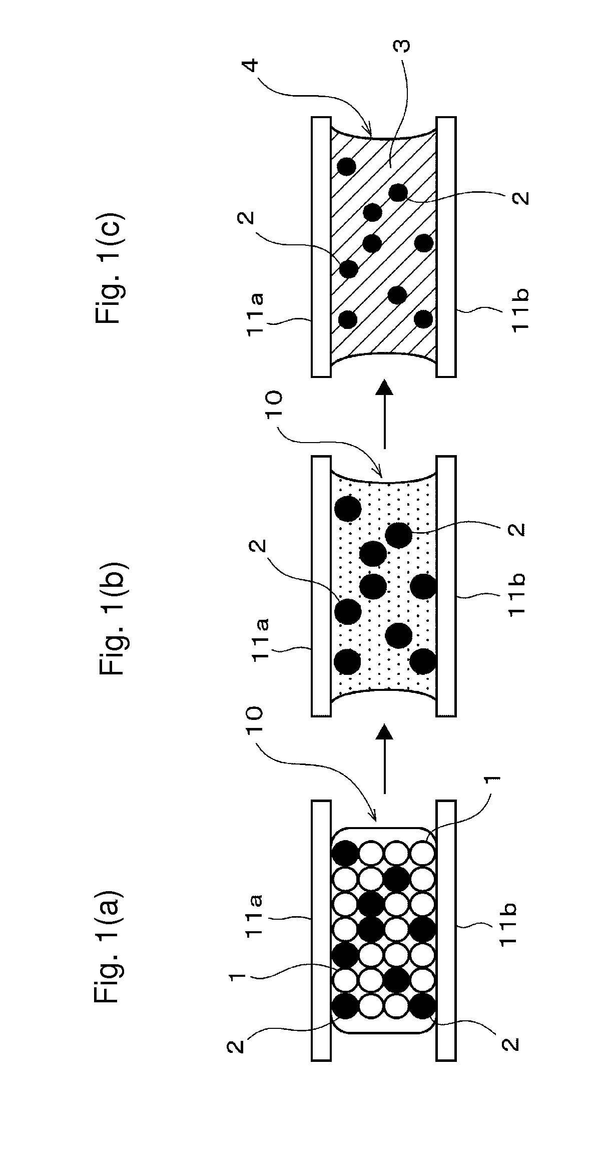
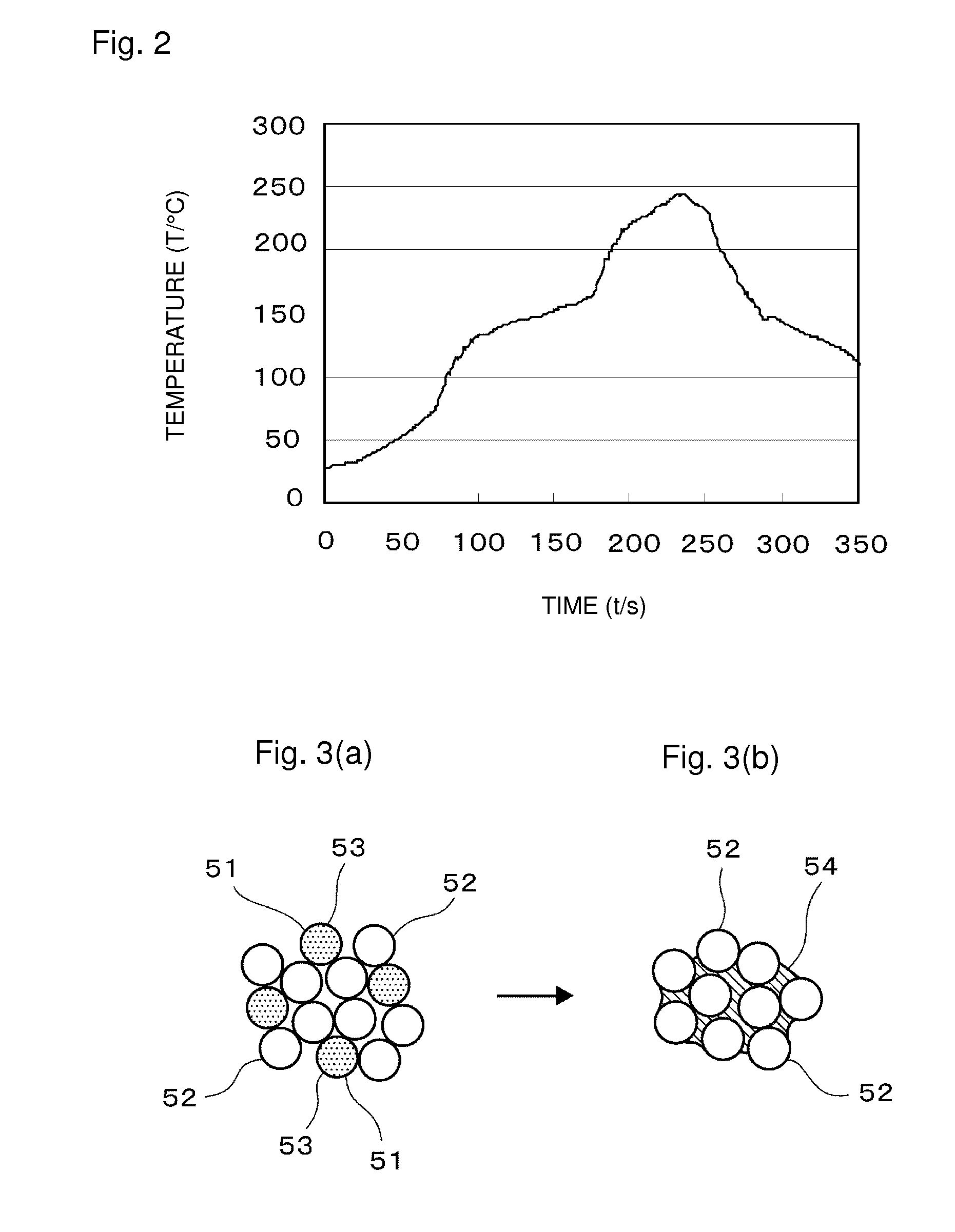
Image

Examples
example 1
[0066]In this example 1, a solder paste was prepared by mixing a first metal powder, a second metal powder and a flux.
[0067]The compounding ratio of the first metal powder and the second metal powder was adjusted so that the volume ratio of the first metal powder / second metal powder was 60 / 40 (i.e. second metal: 40% by volume).
[0068]As the first metal powder, Sn-3Ag-0.5Cu, Sn, Sn-3.5Ag, Sn-0.75Cu, Sn-58Bi, Sn-0.7Cu-0.05Ni, Sn-5Sb, Sn-2Ag-0.5Cu-2Bi, Sn-57Bi-1Ag, Sn-3.5Ag-0.5Bi-8In, Sn-9Zn and Sn-8Zn-3Bi were used as shown in Table 1. The average particle size of the first metal powder was 25 μm.
[0069]In writing of each material described above, for example, the digit (3.5) of “Sn-3.5Ag” represents a value in % by weight of a component concerned (Ag in this case), and the same applies to other materials described above and those described below.
[0070]As the second metal powder, Cu-10Ni, Cu-10Mn, Cu-12Mn-4Ni, Cu-10Mn-1P, a mixed powder of equal amounts of Cu-10Ni and Cu-10Mn, Cu, and C...
example 2
[0098]A powder of Sn-3Ag-0.5Cu was prepared as the first metal powder. The average particle size of the first metal powder was 25 μm.
[0099]Powders of Cu and Cu-10Mn were prepared as the second metal powder. The average particle size of the second metal powder was 15 μm.
[0100]As the flux, one having a compounding ratio of rosin: 74% by weight, diethylene glycol monobutyl ether: 22% by weight, triethanolamine: 2% by weight and hydrogenated castor oil: 2% by weight was prepared.
[0101]A solder paste was prepared by mixing the above-mentioned first metal powder, second metal powder and flux.
[0102]The compounding ratio of the first metal powder and the second metal powder was adjusted so that the volume ratio of the first metal powder / second metal powder was 87 / 13 to 57 / 43 (i.e. second metal powder: 13 to 43% by volume).
[0103]For the compounding ratio of the flux, the ratio of the flux in the entire solder paste was 10% by weight.
[0104]For the solder paste thus prepared, the bonding stren...
example 3
[0112]A powder of Sn-3Ag-0.5Cu was prepared as the first metal powder. The average particle size of the first metal powder was 25 μm.
[0113]A powder of a Cu—Mn alloy with the ratio of Mn of 5 to 30% by weight and a powder of a Cu—Ni alloy with the ratio of Ni of 5 to 20% by weight were prepared as the second metal powder. The average particle size of the second metal powder was 15 w.
[0114]As the flux, one having a compounding ratio of rosin: 74% by weight, diethylene glycol monobutyl ether: 22% by weight, triethanolamine: 2% by weight and hydrogenated castor oil: 2% by weight was prepared.
[0115]A solder paste was prepared by mixing the above-mentioned first metal powder, second metal powder and flux.
[0116]For the compounding ratio of the flux, the ratio of the flux to the entire solder paste was 10% by weight.
[0117]The compounding ratio of the first metal powder and the second metal powder was adjusted so that the volume ratio of the first metal powder / second metal powder was 60 / 40 (...
PUM
| Property | Measurement | Unit |
|---|---|---|
| Fraction | aaaaa | aaaaa |
| Fraction | aaaaa | aaaaa |
| Fraction | aaaaa | aaaaa |
Abstract
Description
Claims
Application Information