Hybrid lithographic method for fabricating complex multidimensional structures

a multi-dimensional structure and hybrid technology, applied in the field of hybrid lithographic methods for fabricating complex multi-dimensional structures, can solve the problems of limited local hierarchical structure made by these techniques, limited local hierarchical structure, and limited microstructure, so as to enhance design and cost cutting, speed and flexibility of flask techniques

Inactive Publication Date: 2012-06-28
MASSACHUSETTS INST OF TECH
View PDF3 Cites 8 Cited by
  • Summary
  • Abstract
  • Description
  • Claims
  • Application Information

AI Technical Summary

Benefits of technology

[0010]Time is also a critical factor in the post baking of a chemically amplified photoresist due to the kinetic nature of the crosslinking reaction. Ideally, the focus laser spike annealing process need be performed within some maximum time to prevent room temperature crosslinking of the exposed resist. In a possible embodiment, temperature control, as described above could be used to lengthen the time that it is possible to perform focus laser spike annealing by cooling. In addition, the exposed resist may he controllably allowed to crosslink at either room or a controlled temperature to allow the reaction to progress to a certain extent, thus lowering the threshold for the laser spike anneal. Alternatively, this could be performed after the laser spike anneal to further set the locally crosslinked areas. In a preferred embodiment, use of a controlled temperature would allow for both the temperature to be raised for controlled crosslinking then lowered to extend the possible time for patterning.
[0012]The ability to pattern 3D periodic architectures with controlled defects according to the invention disclosed herein is important for building progressively more complex photonic or phononic circuits. The speed and flexibility of the FLaSk technique, especially when combined with integrated 3DDW, provides a scalable technique for designing such structures.
[0013]The present invention provides enhanced design and cost cutting in a variety of applications. Examples include local positioning of high surface area structures or mixers within microfluidic channels for lab-on-a-chip applications or designing transformation optics structures with continuously varying index / impedance for optical / acoustic cloaks and hyperlenses.

Problems solved by technology

This places significant limitation on aspects such as features that cross multiple levels, the ability to have multiple material types in close proximity at the same height, and minimum resolution due to registry and stability considerations.
In the aforementioned classification scheme, IL techniques are large area, providing highly uniform structures over areas up to the cm scale by the generation of patterns either by multibeam or phase mask interference, but with little direct control over local defects.
The locally defined hierarchical structures made by these techniques are, however, limited to a uniform microstructure with the same symmetry and filling fraction as the initial 3D template.

Method used


Image

  • Hybrid lithographic method for fabricating complex multidimensional structures
  • Hybrid lithographic method for fabricating complex multidimensional structures
  • Hybrid lithographic method for fabricating complex multidimensional structures

Examples


Embodiment Construction

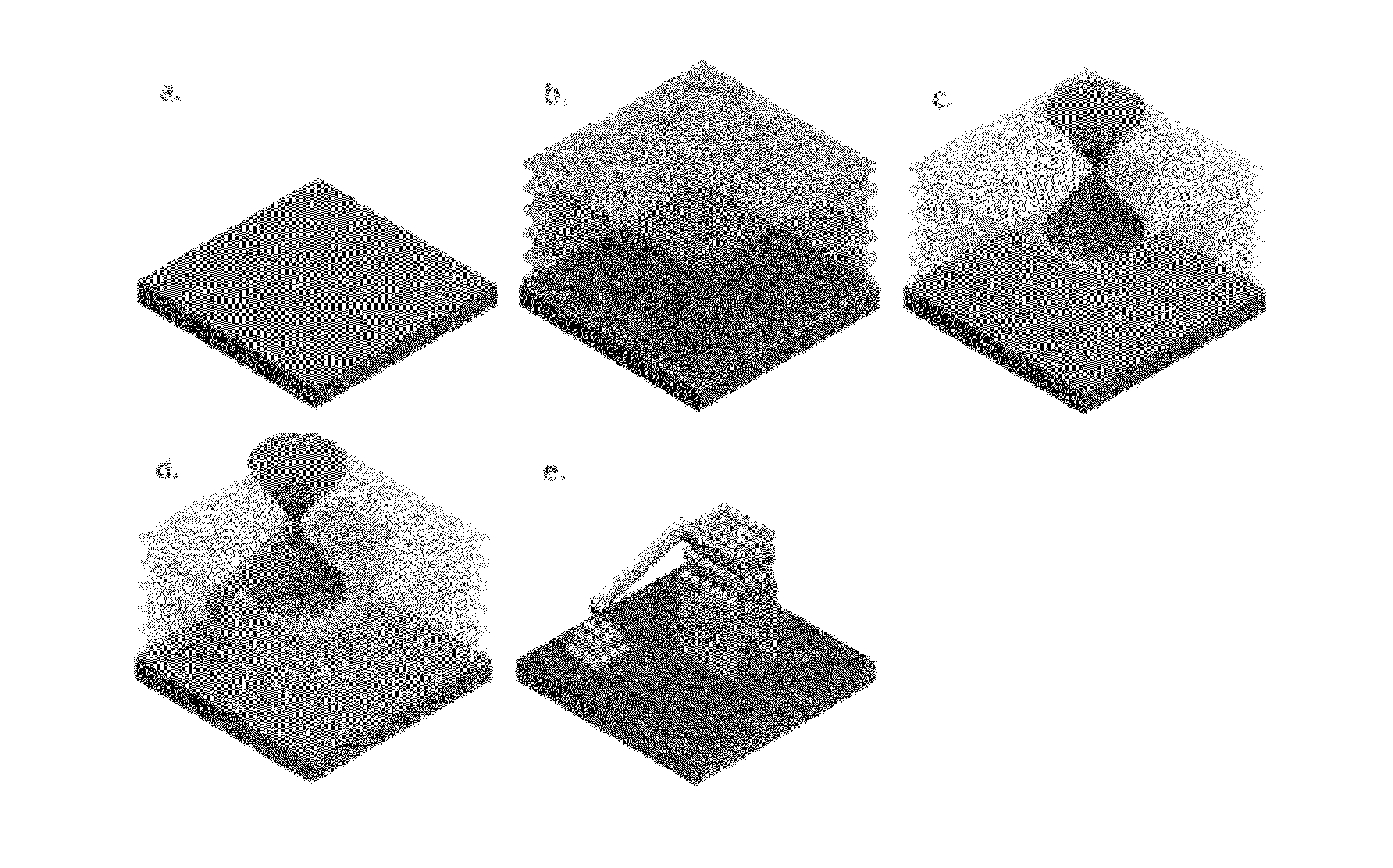
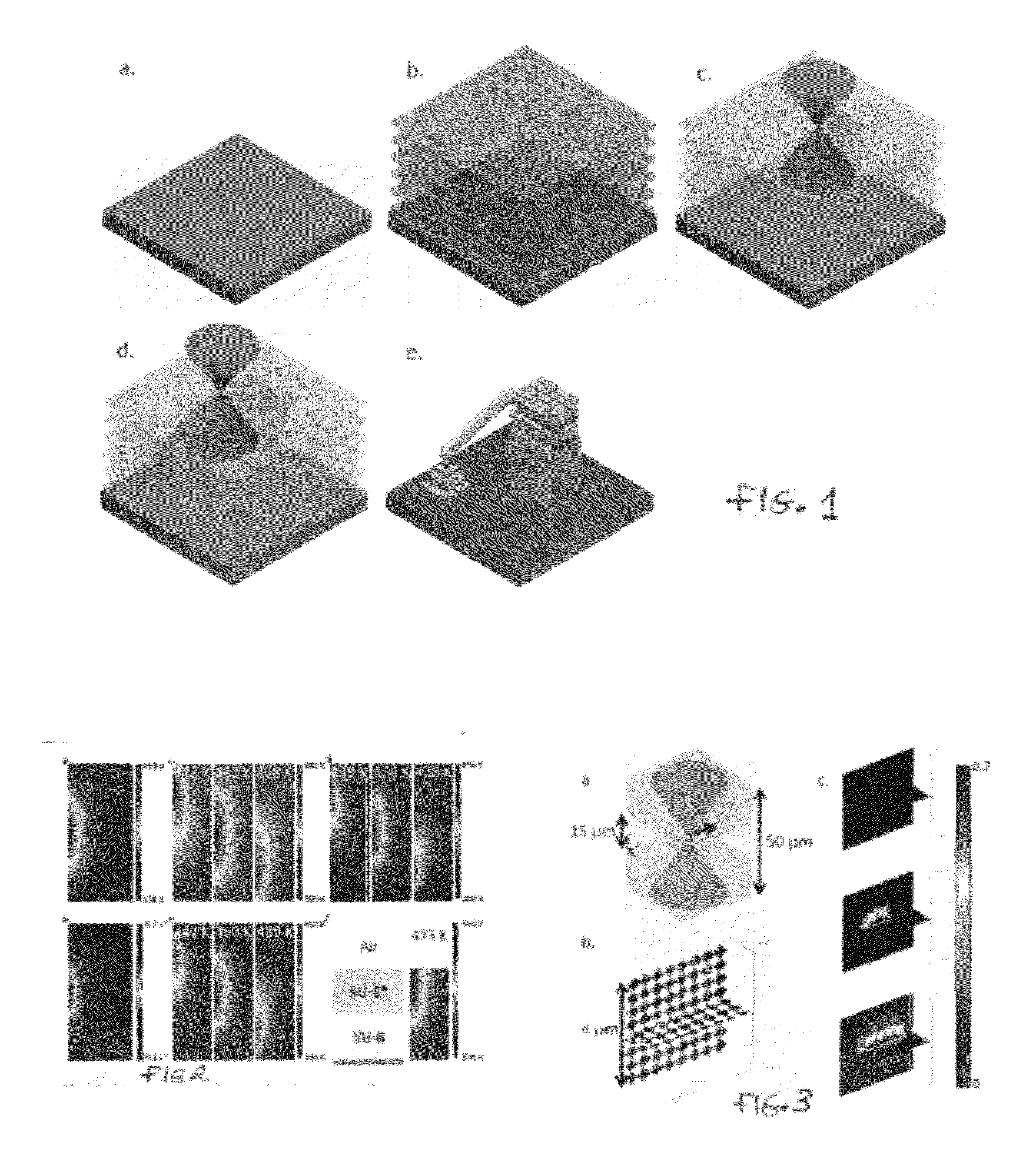
[0026]With reference to FIG. 1, deposition of an active resist layer is shown in FIG. 1a. The resist is exposed by phase mask or multibeam interference lithography as shown in FIG. 1b. FIG. 1c shows a continuous wave heating beam at the wavelength of the dye absorption. FIG. 1d shows the three-dimensional direct write step to define solid features such as supports, defects, or other structures not part of the interference lithography pattern. FIG. 1e shows the development of the patterned structure without additional post-baking.

[0027]FIG. 1 thus shows an idealized schematic for the eventual capabilities of FLaSk. In FLaSk, the broadly focused rastering laser beam of LSA is replaced with a tightly focused source inside of the photoresist. This allows for 3D direct write LSA with up to sub-micron 195 features possessing hierarchical substructure defined by the IL step. Ideally, this process occurs without the DW beam performing additional photoinitiation, thus maintaining the contras...


PUM

PropertyMeasurementUnit
poweraaaaaaaaaa
glass transition temperatureaaaaaaaaaa

Abstract

Lithographic Method. The method fabricates complex structures and includes depositing a photoresist onto a substrate, the photoresist including a predominantly thermal band of optical absorption possibly due to the incorporation of a doping agent. A three-dimensional pattern is generated within the resist using a first wavelength of light to effect activation of a photoinitiator to produce a latently photostructured resist. Focused laser spike annealing of the photostructured resist with a second wavelength of light selected to be absorbed by the thermally absorbing band to accelerate the photoinduced reaction in the resist is provided. Three-dimensional direct writing may be performed within the resist to define features not part of the interference pattern and the resist is developed to produce the complex structure.

Description

[0001]This application claims priority to provisional patent application Ser. No. 61 / 361,648 filed Jul. 6, 2010, the contents of which are incorporated herein by reference.[0002]This invention was made with government support under Grant No. W911NF-07-D-0004 awarded by the Army Research Office. The government has certain rights in this invention.BACKGROUND OF THE INVENTION[0003]This invention relates to lithography and more particularly to a lithographic method combining large area interference lithography with local area direct write focused laser spike annealing (FLaSk).[0004]In order to advance lithographic capabilities for future applications, innovative strategies must be available in a scalable and cost-effective set of techniques. All lithographic techniques can be considered as either large or small area with respect to the features they pattern. While this is a rather simplistic classification scheme, it illustrates the dichotomy of lithographic strategies, namely: speed ve...

Claims


Application Information

Patent Timeline
Patent Type & Authority Applications(United States)
IPC IPC(8): G03F7/20
CPCB82Y10/00B82Y40/00G03F7/70375G03F7/0002G03F7/203G03F1/20
Inventor SINGER, JONATHAN PHILLIPLEE, JAE-HWANGKOOI, STEVEN E.THOMAS, EDWIN LORIMER
Owner MASSACHUSETTS INST OF TECH
Why Eureka
Try Eureka