
Electric cable with bending sensor and monitoring system and method for detecting bending in at least one electric cable

a monitoring system and electric cable technology, applied in the direction of cables, insulated conductors, force measurement by measuring optical property variation, etc., can solve the problem of general non-operational checks, and achieve the effect of effective periodic maintenance and high mechanical stress

Active Publication Date: 2012-07-12
PRYSMIAN SPA
View PDF3 Cites 28 Cited by
  • Summary
  • Abstract
  • Description
  • Claims
  • Application Information

AI Technical Summary

Benefits of technology

[0017]It would be particularly advantageous to record, during the cable work, dynamic events that induce compressive (negative strain) peaks, which can however damage the cable by fatigue. Such a monitoring could prevent unexpected out-of-service events and save relevant costs. Also, it would be advantageous to localize the portion of a cable unduly bent because of a dropping from or a squeezing by the apparatus where the cable operates.
[0041]Given a minimum bending radius for an electric cable, which generally corresponds to the smallest radius of curvature, ρmin, which is allowed for the cable in order to avoid any permanent damage, the neutral region can be defined as the region where the strain sensor undergoes to an elongation not larger than 2%, and preferably not larger than 1%, due to the bending at radii of curvature not smaller than ρmin. Positioning of the strain optical fibre within the geometrical axis substantially coincident, over a certain bending radius, with the neutral region prevents the optical fiber rupture or permanent damage due to cable bending.
[0048]The Applicant has found that it is advantageous to surround the strain optical fibre with a protective sheath to improve mechanical resistance to lateral loads, said protective sheath directly contacting the optionally buffered optical fibre of the strain sensor. Preferably, the protective sheath comprises a fibre reinforced composite.

Problems solved by technology

Periodic checks of the cable conditions could be made “off-line” with a cable not in use or even removed from the equipment on which it was mounted, but in the practice such checks are generally not carried out because of the loss of working time due to the necessary stop of the equipment or apparatus containing the cable.

Method used


Image

  • Electric cable with bending sensor and monitoring system and method for detecting bending in at least one electric cable
  • Electric cable with bending sensor and monitoring system and method for detecting bending in at least one electric cable
  • Electric cable with bending sensor and monitoring system and method for detecting bending in at least one electric cable

Examples


Embodiment Construction

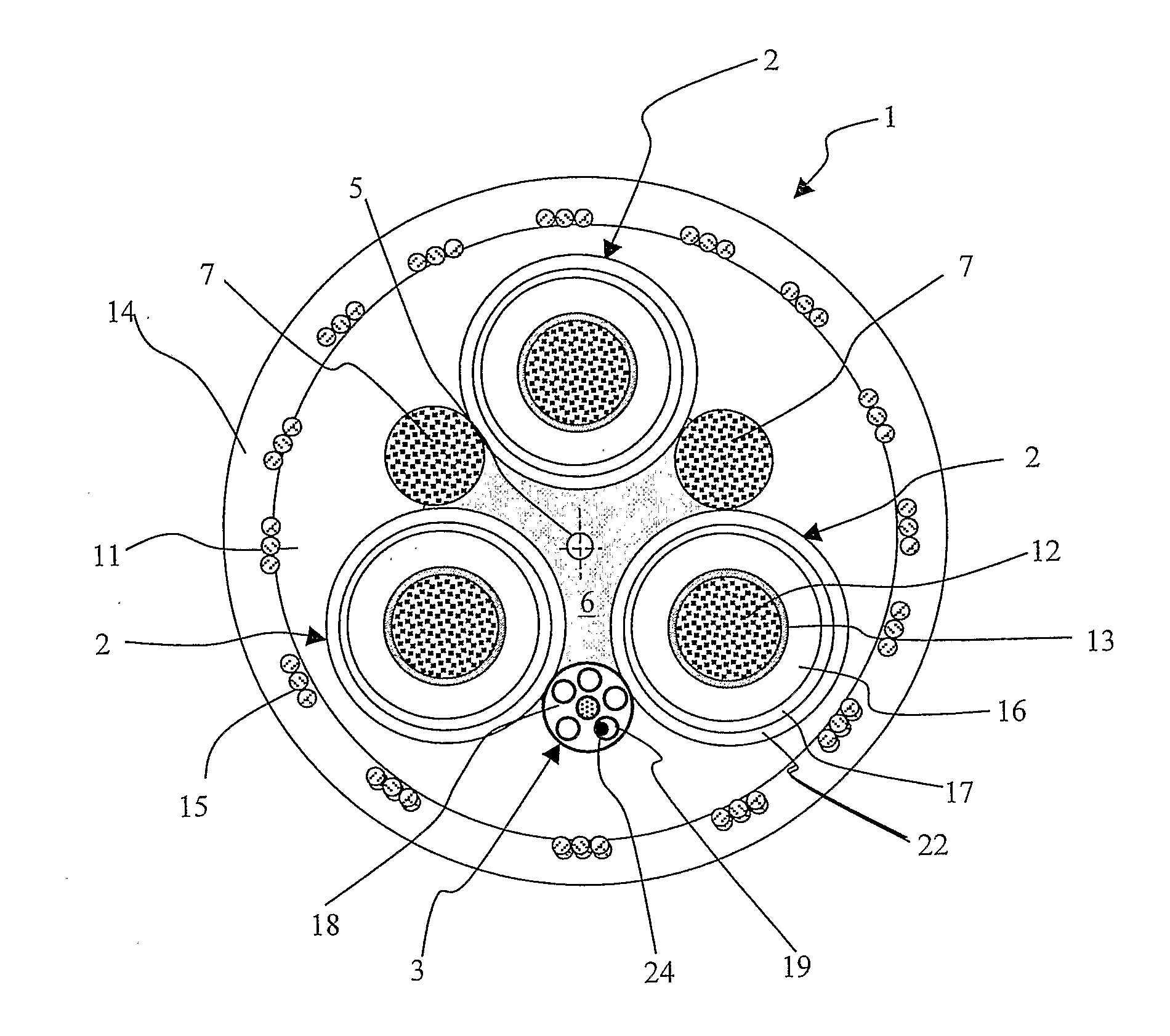
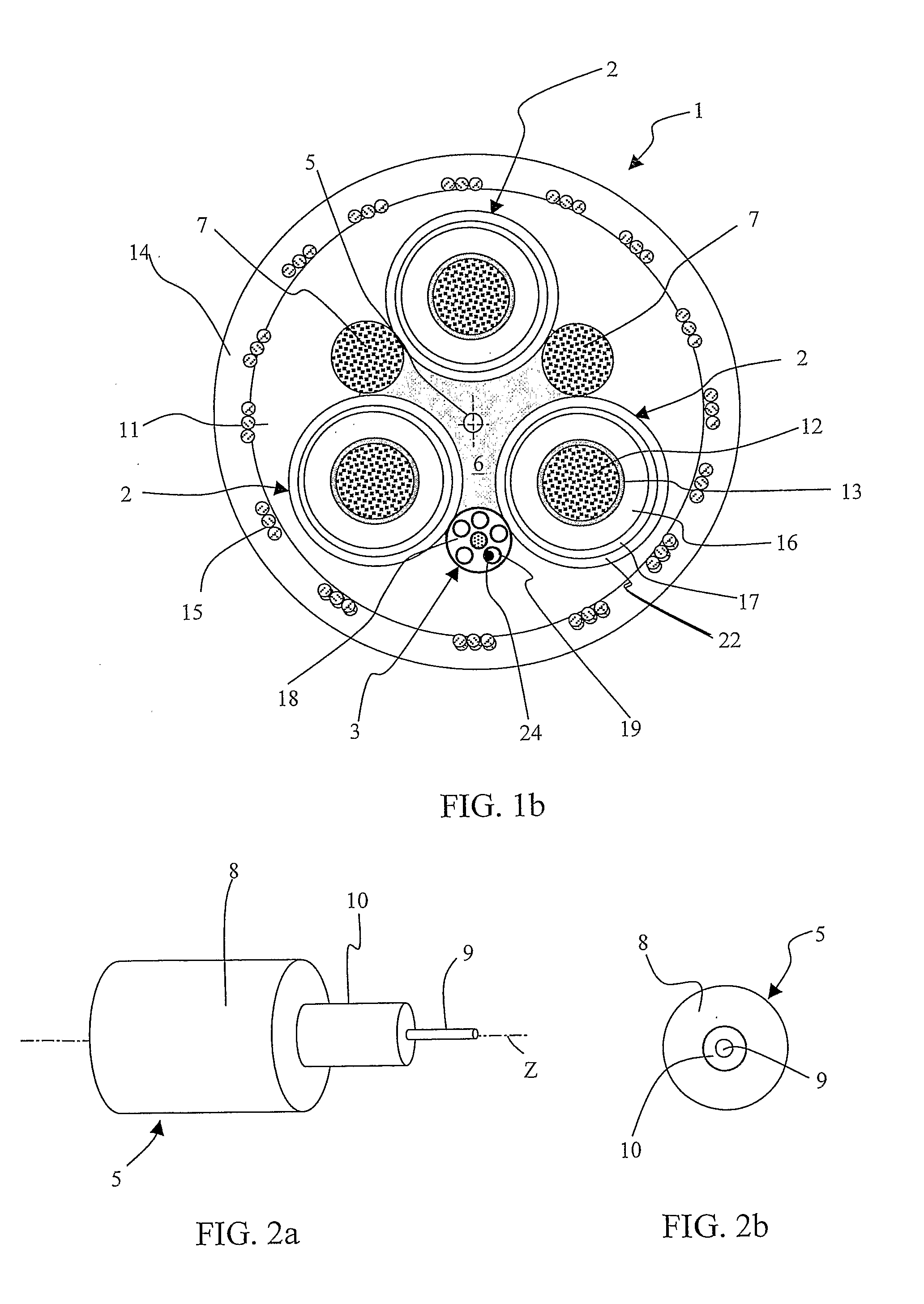
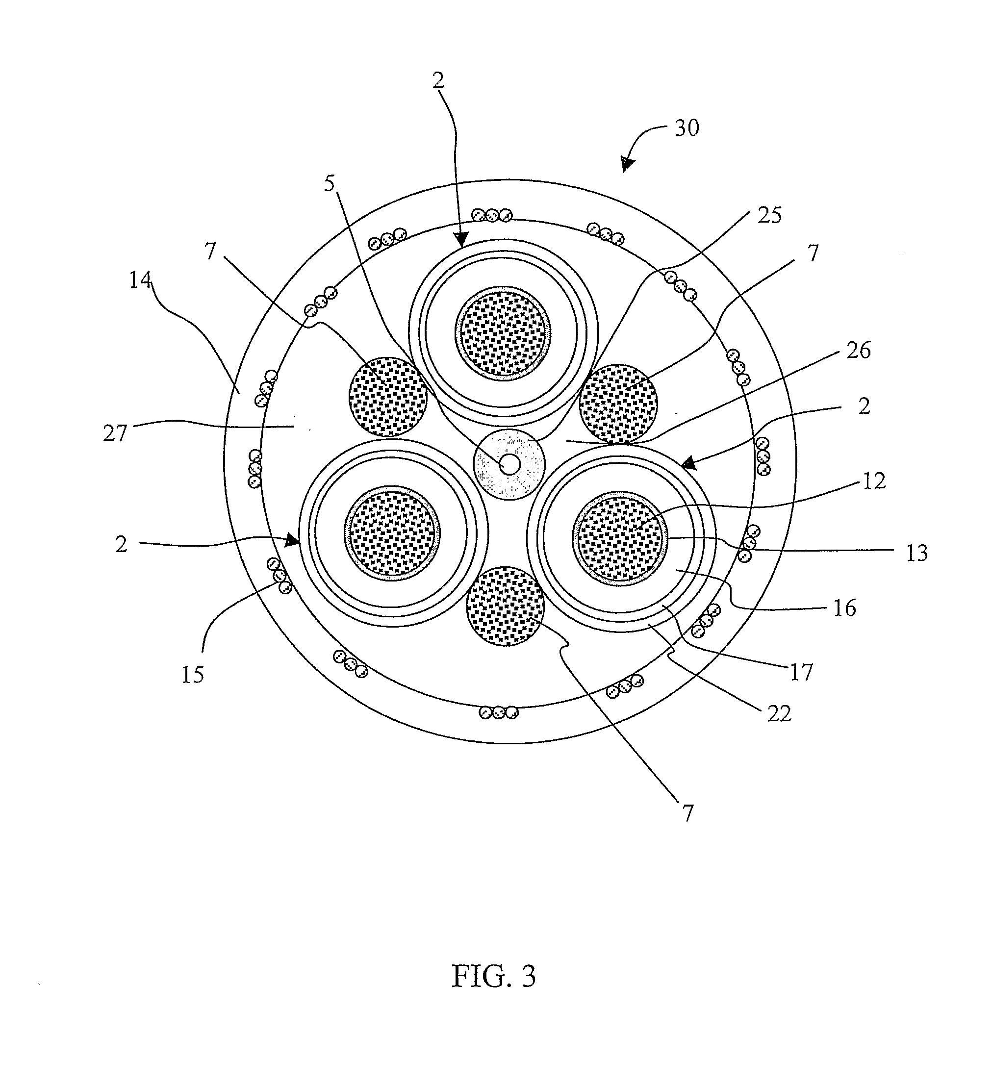
[0072]FIGS. 1a and 1b illustrates, respectively, a perspective view and a cross-sectional view of an electric cable, according to an embodiment of the present invention. The cable shown of this embodiment can be suitable for heavy-duty applications, more particularly for mobile installations. Cable 1 is a round cable comprising three cores 2 radially arranged about a central longitudinal axis Z (visible in FIG. 1a) of the cable. The cores 2 can provide three-phase power transmission. Cable 1 can be a low or medium voltage power cable, where low voltage indicates a voltage of up to 1 kV and medium voltage indicates a voltage of from 1 kV to 60 kV. Each core 2 comprises an electrical conductor 12, for example a copper conductor formed by a bundle of tinned or bare copper electrical wires stranded together according to conventional methods. In radial external position with respect to each electrical conductor 12, an inner semi-conductive layer 13, an insulating layer 16, an outer semi-...


PUM

PropertyMeasurementUnit
elongationaaaaaaaaaa
temperaturesaaaaaaaaaa

Abstract

A method for monitoring at least the bending strain of at least one electric cable provided with at least one peripheral mechanically non-symmetric strength member is provided.

Description

FIELD OF THE INVENTION[0001]The present invention relates to an electric cable with an integrated strain sensor, suitable in particular for the measurement of static and dynamic strains, in particular bending strains.[0002]The present invention is directed also to a monitoring method and system for measuring bending in at least one electric cable.[0003]The present invention further relates to a monitoring system and method for detecting bending in a plurality of electric cables. In particular, the present invention concerns monitoring system and method using Brillouin backscattering techniques for monitoring the bending strain a plurality of electric cables installed in mobile equipments.BACKGROUND OF THE INVENTION[0004]Electric cables, in particular for heavy-duty applications and / or for mobile installations, such as mobile harbour cranes, ship-to-shore container cranes, ship un-loaders, spreaders, and mining and tunnelling equipment, are specifically designed to withstand harsh en...

Claims


Application Information

Patent Timeline
Patent Type & Authority Applications(United States)
IPC IPC(8): G01L1/24
CPCH01B7/32G01L1/242D07B1/145D07B2201/2096D07B2301/5577D07B1/147G01B11/18
Inventor KEMNITZ, CARSTENSARCHI, DAVIDEKNUEPFER, BERNDCOLETTA, GIACOMOCARL, ARND-GUENTHERKITTEL, THOMASEWALD, REINER
Owner PRYSMIAN SPA
Learn More