Light-reflective conductive particle, anisotropic conductive adhesive and light-emitting device

a technology of anisotropic conductive adhesive and light-emitting device, which is applied in the direction of non-macromolecular adhesive additives, metal/alloy conductors, and conductors, etc., can solve the problems of deteriorating light-emitting efficiency of led elements b>33/b>, and achieve the effect of improving light-emitting efficiency

Inactive Publication Date: 2012-07-12
DEXERIALS CORP
View PDF1 Cites 14 Cited by
  • Summary
  • Abstract
  • Description
  • Claims
  • Application Information

AI Technical Summary

Benefits of technology

[0012]The light-reflective conductive particle of the present invention for an anisotropic conductive adhesive used for anisotropic conductive connection of a light-emitting element to a wiring board is formed from a core particle coated with a metal material and a light-reflecting layer which has a white to grey color and is formed from light-reflective inorganic particles having a refractive index of 1.52 or more on a surface of the core particle. Further, the anisotropic conductive adhesive of the present invention comprises this light-reflective conductive particle dispersed in a thermosetting resin composition that forms a cured product having a light transmittance (JIS K7105) of 80% or more at a light path length of 1 cm to visible light having a wavelength of 380 to 780 nm. Therefore, a light-emitting device obtained using the anisotropic conductive adhesive of the present invention does not discolor even if the anisotropic conductive adhesive is cured. Moreover, since the included light-reflective conductive particles have a low dependence of the reflecting property to the wavelength of the visible light, light-emitting efficiency can be improved, and the emission color of the light-emitting element can be reflected as that color without change.

Problems solved by technology

However, for the light-emitting device illustrated in FIG. 4, there is the problem that, among the light emitted by the LED element 33, the light having a wavelength of 400 to 500 nm that is output to the upper face side is absorbed by the gold wire, and a part of the light output to the lower face side is absorbed by the die bond adhesive 32, whereby the light-emitting efficiency of the LED element 33 deteriorates.

Method used


Image

  • Light-reflective conductive particle, anisotropic conductive adhesive and light-emitting device
  • Light-reflective conductive particle, anisotropic conductive adhesive and light-emitting device
  • Light-reflective conductive particle, anisotropic conductive adhesive and light-emitting device

Examples


example 1

(Production of Light-Reflective Conductive Particles)

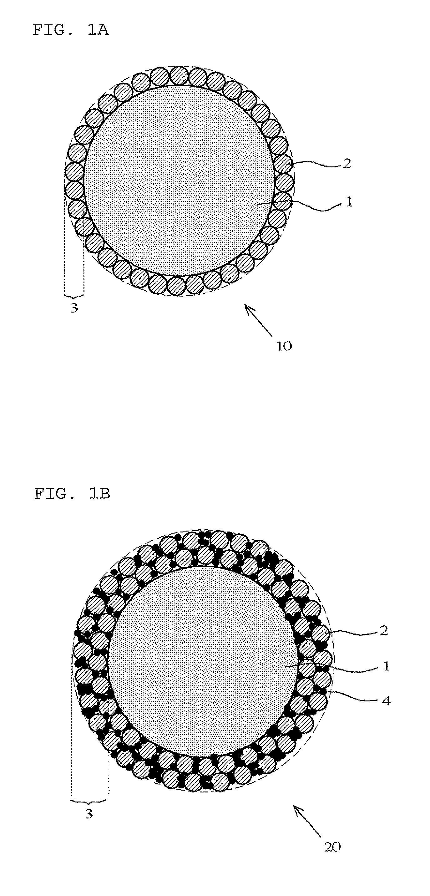
[0050]The light-reflective conductive particles of Example 1 were obtained by adding 4 parts by mass of a titanium oxide powder having an average particle size of 0.5 μm (KR-380, Titan Kogyo, Ltd.) and 20 parts by mass of Au-coated resin conductive particles having a brown appearance and an average particle size of 5 μm (particles formed by coating a 0.2 μm-thick electroless gold plating on spherical acrylic resin particles having an average particle size of 4.6 μm (Bright 20GNB4.6 EH, Nippon Chemical Industrial Co., Ltd.)) to a mechanofusion apparatus (AMS-GMP, Hosokawa Micron Corporation), and depositing an approximately 0.3 μm-thick light-reflecting layer formed from the titanium oxide particles on the surface of the conductive particles under conditions of a rotation speed of 1,000 rpm and a rotation time of 20 minutes. The appearance of these light-reflective conductive particles was grey.

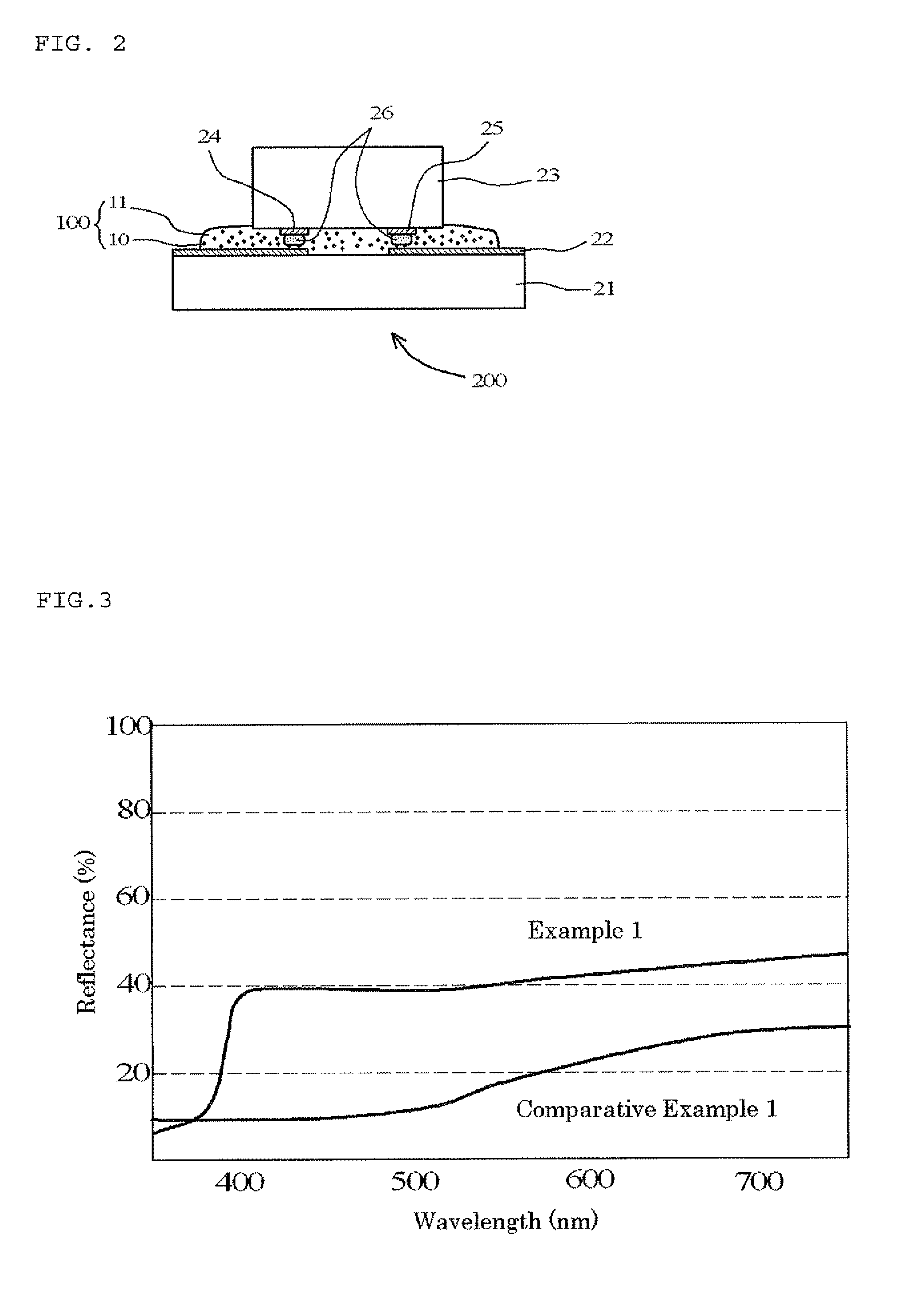
(Light Reflectance Evaluation Test)

[0...

example 2

[0056]Light-reflective conductive particles having a grey appearance, and an anisotropic conductive adhesive, were obtained in the same manner as in Example 1, except that Ni-coated resin conductive particles having an average particle size of 5.0 μm (52NR-4.6 EH, Nippon Chemical Industrial Co., Ltd.) were used instead of Au-coated resin conductive particles. Further, a light reflectance evaluation test and an electrical properties (continuity reliability, insulation reliability) evaluation test were also carried out in the same manner as in Example 1. The obtained results are shown in Table 1.

example 3

[0057]Light-reflective conductive particles having a grey appearance were obtained by adding 4 parts by mass of a titanium oxide powder having an average particle size of 0.5 μm (KR-380, Titan Kogyo, Ltd.), 3 parts by mass of polystyrene (PS) particles having an average particle size of 0.2 μm (Glossdell 204S, Mitsui Chemicals, Inc.) as adhesive particles, and 20 parts by mass of conductive particles having an average particle size of 5 μm (particles formed by coating a 0.2 μm-thick electroless gold plating on spherical acrylic resin particles having an average particle size of 4.6 μm (Bright 20GNB4.6 EH, Nippon Chemical Industrial Co., Ltd.) to a mechanofusion apparatus (AMS-GMP, Hosokawa Micron Group), and depositing an approximately 1 μm-thick light-reflecting layer formed from styrene and titanium oxide particles on the surface of the conductive particles under conditions of a rotation speed of 1,000 rpm and a rotation time of 20 minutes. Then, an anisotropic conductive adhesive...


PUM

PropertyMeasurementUnit
refractive indexaaaaaaaaaa
thicknessaaaaaaaaaa
light path lengthaaaaaaaaaa

Abstract

A light-reflective conductive particle for an anisotropic conductive adhesive used for anisotropic conductive connection of a light-emitting element to a wiring board includes a core particle coated with a metal material and a light-reflecting layer formed from light-reflective inorganic particles having a refractive index of 1.52 or more on a surface of the core particle. Examples of the light-reflective inorganic particles having a refractive index of 1.52 or more include titanium oxide particles, zinc oxide particles, or aluminum oxide particles.

Description

TECHNICAL FIELD[0001]The present invention relates to a light-reflective conductive particle for an anisotropic conductive adhesive used for anisotropic conductive connection of a light-emitting element to a wiring board, an anisotropic conductive adhesive containing the same, and a light-emitting device formed by using this adhesive to mount a light-emitting element to a wiring board.BACKGROUND ART[0002]Light-emitting devices that use a light-emitting diode (LED) element are widely used. Older-type light-emitting devices are configured by, as illustrated in FIG. 4, joining an LED element 33 to a substrate 31 with a die bond adhesive 32, wire-bonding a p electrode 34 and an n electrode 35 on an upper face of the LED element 33 to a connection terminal 36 on the substrate 31 with a gold wire 37, and then sealing the whole of the LED element 33 with a transparent mold resin 38. However, for the light-emitting device illustrated in FIG. 4, there is the problem that, among the light emi...

Claims


Application Information

Patent Timeline
Patent Type & Authority Applications(United States)
IPC IPC(8): H01L33/60H01B1/22H01B1/00
CPCC08K3/08H01L2924/12041C08L23/02C09J9/02C09J11/04C09J123/02H01L33/60H01L2224/48091H01L2924/01004H01L2924/01012H01L2924/01046H01L2924/01057H01L2924/01078H01L2924/01079C08K9/02H01L2924/01047H01L2924/01015H01L2924/07811H01L24/45H01L2924/01029H01L2924/00013H01L2224/16227H01L2224/45147H01L2224/16225H01L2224/32225H01L2224/48227H01L2224/73204H01L2224/73265H01L2224/2949H01L2224/2939H01L2224/29455H01L2224/29447H01L2224/29644H01L2224/29647H01L2224/29655C08G59/42C08L63/00H01L24/16H01L24/29H01L24/32H01L24/83H01L2224/13144H01L2224/2929H01L2224/29344H01L2224/29347H01L2224/29355H01L2224/29386H01L2224/29499H01L2224/83851H01L2924/01019H01L2224/29444H01L2224/45144H01L2924/00014H01L2924/00H01L2224/13099H01L2224/13599H01L2224/05599H01L2224/05099H01L2224/29099H01L2224/29599H01L2924/00012H01L2924/0665H01L2924/00011H01L2924/181H01L24/73H01L2224/29486H01L2224/29498H01L2924/05341H01L2924/05432H01L2924/0542
Inventor NAMIKI, HIDETSUGUKANISAWA, SHIYUKIUMAKOSHI, HIDEAKI
Owner DEXERIALS CORP
Why Eureka
Try Eureka