Supercharge Your Innovation With Domain-Expert AI Agents!

Injector And Method For Reducing Nox Emissions From Boilers, IC Engines and Combustion Processes

a technology of injector and combustion process, which is applied in the direction of machines/engines, chemical/physical processes, process and machine control, etc., can solve the problems of increased fuel economy offset by undesired pollution emissions, gaseous ammonia presents storage and handling concerns, and ammonia presence, so as to reduce nox emissions and maximize the efficiency of the scr process

Inactive Publication Date: 2012-07-12
PEERLESS MFG CO
View PDF15 Cites 29 Cited by
  • Summary
  • Abstract
  • Description
  • Claims
  • Application Information

AI Technical Summary

Benefits of technology

[0017]It is an objective of the present invention to provide a system and method for reducing NOx emissions that maximize the efficiency of the SCR process without the complexity of controlling two separate processes, as in the combined SNCR / SCR processes.
[0018]It is also an objective of the present invention to provide a system and method for reducing NOx emissions that minimize the quantity of water injected into the boiler and that are capable of utilizing standard industrial concentrations of urea in solution.
[0019]It is further an objective of the present invention to provide a system and method for reducing NOx emissions that are capable of utilizing safe urea reagent by atomizing a urea solution for fast conversion to ammonia at a point of injection into a combustion zone or steam generation zone of a boiler.

Problems solved by technology

However, this increase in fuel economy is offset by undesired pollution emissions, specifically in the form of oxides of nitrogen (“NOx”).
On the other hand, gaseous ammonia presents storage and handling concerns due to its hazardous nature.
Many small industrial and commercial institutions, such as hospitals, schools and food processors, have restrictions on the presence of ammonia due to safety and health concerns.
However, use of the aqueous urea solution involves many disadvantages.
Urea is highly corrosive and attacks mechanical components of the SCR systems, such as the injectors used to inject the urea mixture into the exhaust gas stream.
Solidified urea may foul moving parts of the injector and clog any openings, rendering the injector unusable.
In addition, if the urea mixture is not finely atomized, urea deposits will form in the catalytic reactor, inhibiting the action of the catalyst and thereby reducing the SCR system effectiveness.
However, high injection pressures often result in over-penetration of the injector spray plume into the exhaust stream, causing the plume to impinge on the inner surface of the exhaust pipe opposite the injector.
Over-penetration leads to inefficient use of the urea mixture and requires that much more be used.
In addition, poor atomization of the liquid urea reagent can cause reagent to deposit on boiler, exhaust duct or downstream SCR catalyst surfaces causing fouling.
Several urea systems, therefore, use large and costly evaporators and conversion reactors or exhaust bypass ducts to convert urea to ammonia on site prior to injection into the exhaust duct for reaction across a catalyst.
This requires large quantities of heat or power to convert urea to ammonia and can result in large quantities of ammonia gas still being present on site.
The application of these techniques to small institutional commercial or industrial boilers presents cost, space and operating issues.
However, the structure proposed by Peter-Hoblyn is likely prone to plugging by urea decomposition products.

Method used


Image

  • Injector And Method For Reducing Nox Emissions From Boilers, IC Engines and Combustion Processes
  • Injector And Method For Reducing Nox Emissions From Boilers, IC Engines and Combustion Processes
  • Injector And Method For Reducing Nox Emissions From Boilers, IC Engines and Combustion Processes

Examples


Embodiment Construction

[0047]The ensuing detailed description provides exemplary embodiments only, and is not intended to limit the scope, applicability, or configuration of the invention. Rather, the ensuing detailed description of the exemplary embodiments will provide those skilled in the art with an enabling description for implementing an exemplary embodiment of the invention. It should be understood that various changes may be made in the function and arrangement of elements without departing from the spirit and scope of the invention as set forth in the appended claims.

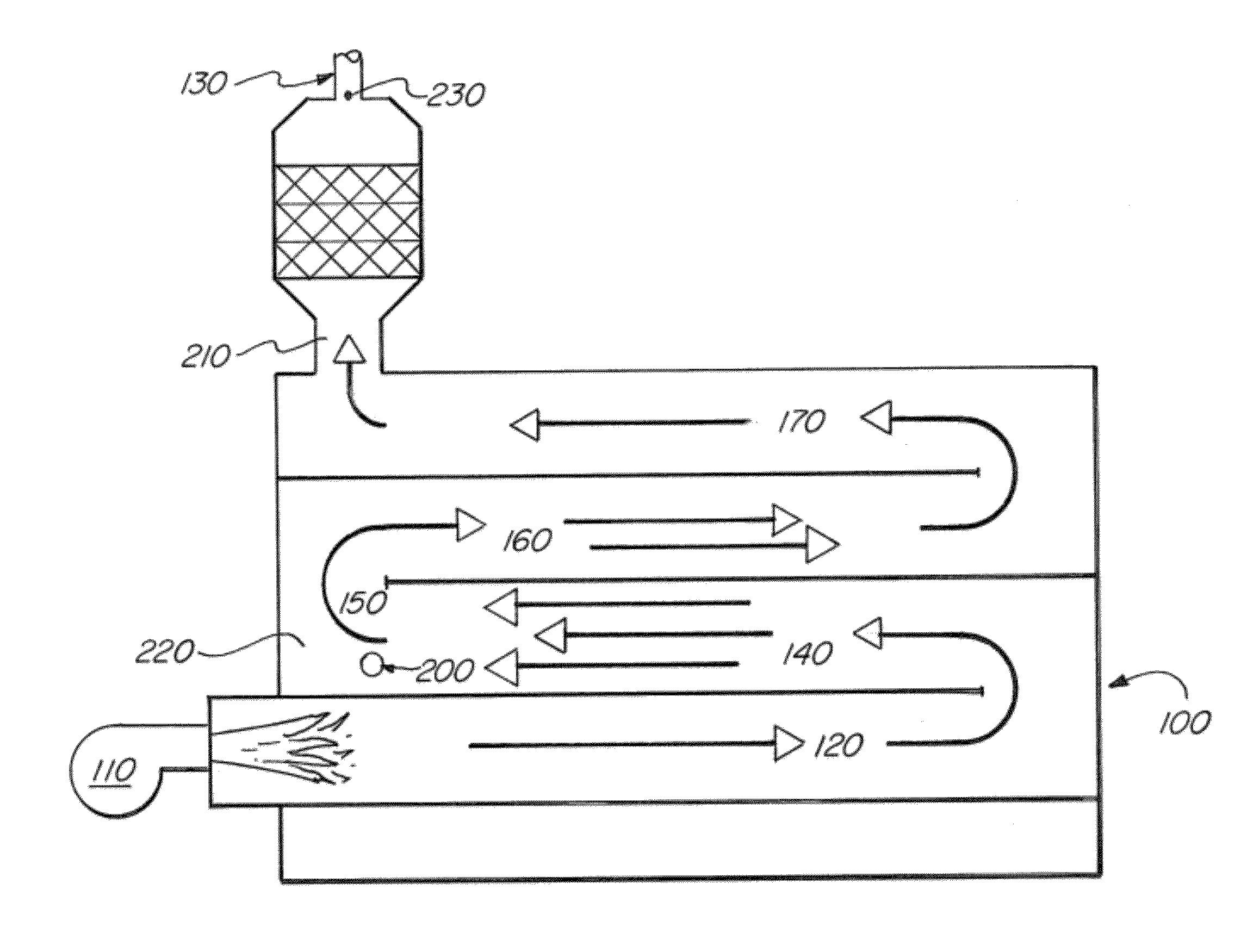
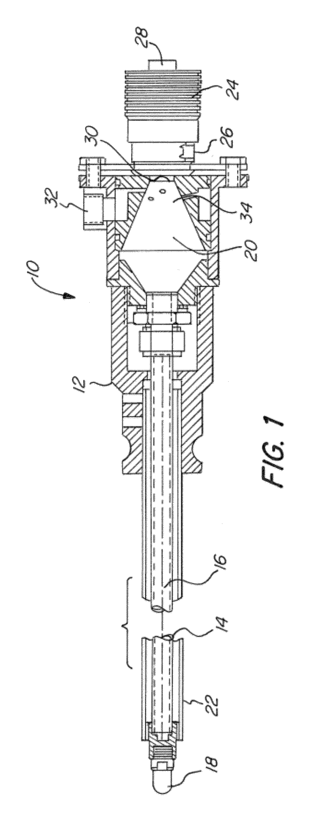
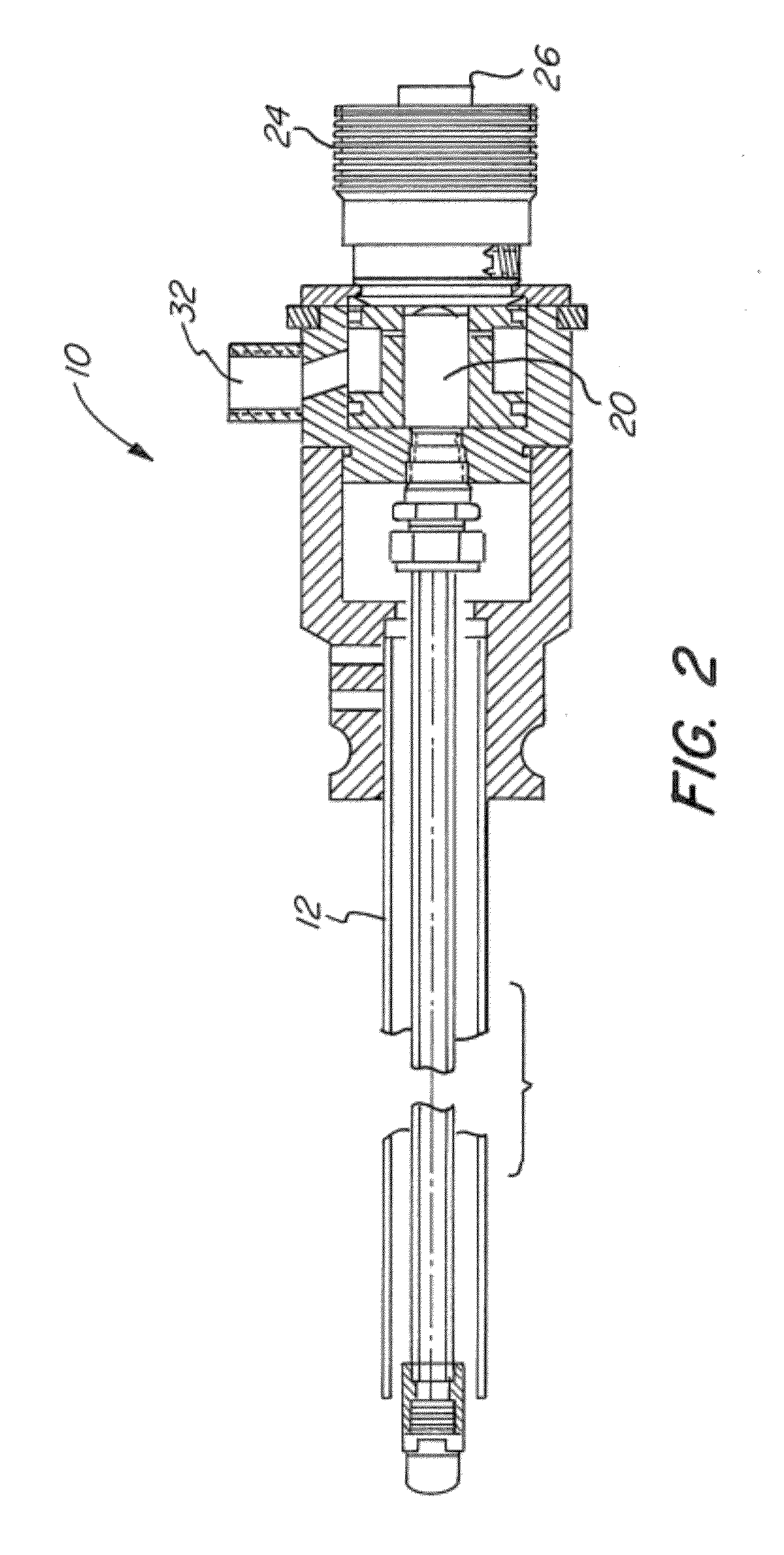
[0048]The present invention is directed to the reduction of nitrogen oxide emissions produced by lean burn engines including boilers, combustors, compression engines and gas turbines firing hydrocarbon based fuels or biomass fuels alone, or in combination. In particular the present invention provides a method and apparatus for injecting urea solutions into the heat extraction zone of a small combustion source, such as a fire tube boi...


PUM

PropertyMeasurementUnit
inlet pressureaaaaaaaaaa
air pressureaaaaaaaaaa

Abstract

A system and method of reducing NOx emissions from a lean burn combustion source is provided. The system includes at least one injection lance having a elongated shaft with distal and proximal ends, a metering valve positioned at the distal end, an atomization chamber positioned between the metering valve and the distal end, a storage chamber for containing a reagent fluidly connected to the metering valve, an injection tip positioned at the proximal end for delivering the reagent, and at least one air port for supplying air to the atomization chamber. The injection lance is positioned in the combustion source, and the reagent is supplied from the storage chamber to the injection lance at an inlet pressure. The reagent is then injected into the combustion source via the injection lance, wherein a temperature of the reagent prior to the injection is maintained below a hydrolysis temperature of the reagent.

Description

CROSS-REFERENCE TO RELATED APPLICATIONS[0001]This application claims the benefit of, under 35 U.S.C. 119(e), U.S. Provisional Patent Application No. 61 / 420,642, filed Dec. 7, 2010, which application is hereby incorporated by reference herein.FIELD OF THE INVENTION[0002]The present invention relates generally to the reduction of oxides of nitrogen (NOx) emissions produced by lean burn combustion sources. In particular, the present invention provides methods and apparatus for injecting a reagent, such as an aqueous urea solution, via an air assisted injection lance such that a temperature of the reagent prior to the injection is maintained below a hydrolysis temperature of the reagent to prevent the reagent from decomposing and depositing on the injector parts. The reagent is injected between an outlet of a second pass and an entrance to a third pass of the combustion source to use the heat of the combustion gases to decompose the urea reagent to ammonia without the need for external ...

Claims


Application Information

Patent Timeline
Patent Type & Authority Applications(United States)
IPC IPC(8): B01D53/56
CPCF23J7/00F23J15/003B01D53/8631B01D53/9431B01D2251/2067Y02T10/24F01N3/2066F01N2610/02F01N2610/08F01N2610/1453C10L10/00B01D2258/012Y02T10/12
Inventor LINDEMANN, SCOTT H.HARTEL, BRUCE E.DALE, JOHN N.BRODERICK, JEFFREY MICHAELVALENTINE, JAMES M.
Owner PEERLESS MFG CO
Features
  • R&D
  • Intellectual Property
  • Life Sciences
  • Materials
  • Tech Scout
  • Unparalleled Data Quality
  • Higher Quality Content
  • 60% Fewer Hallucinations
Learn More