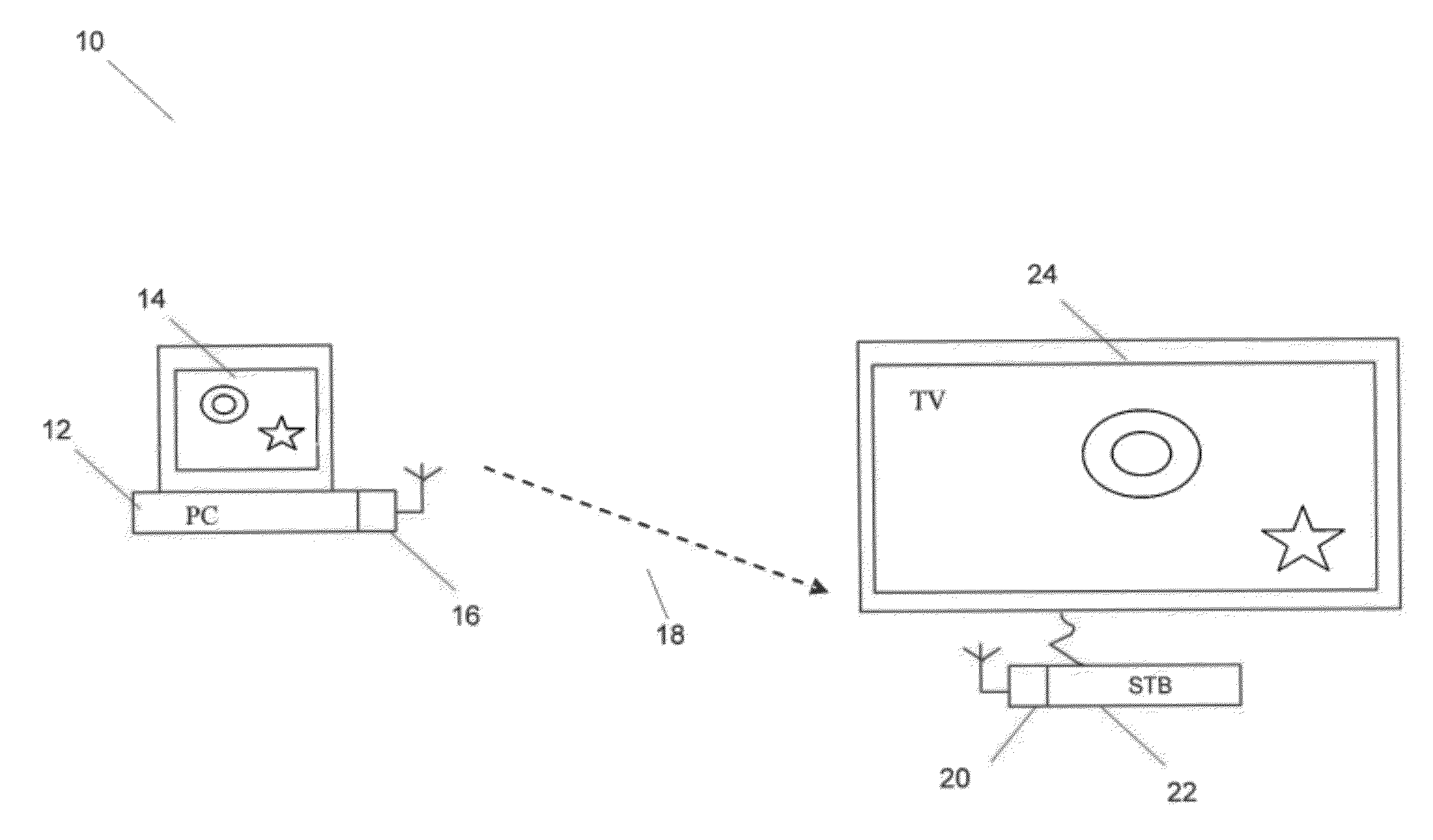
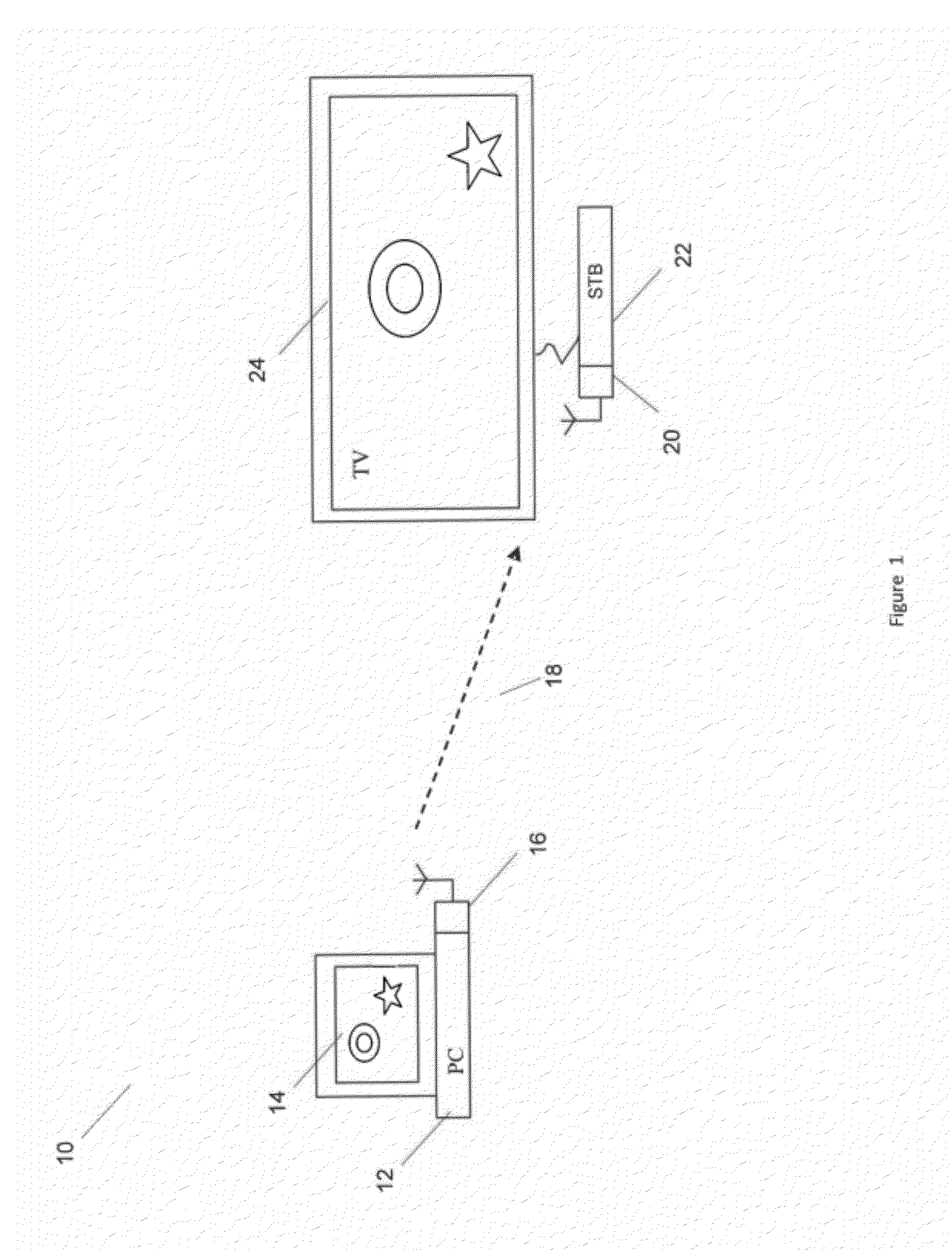
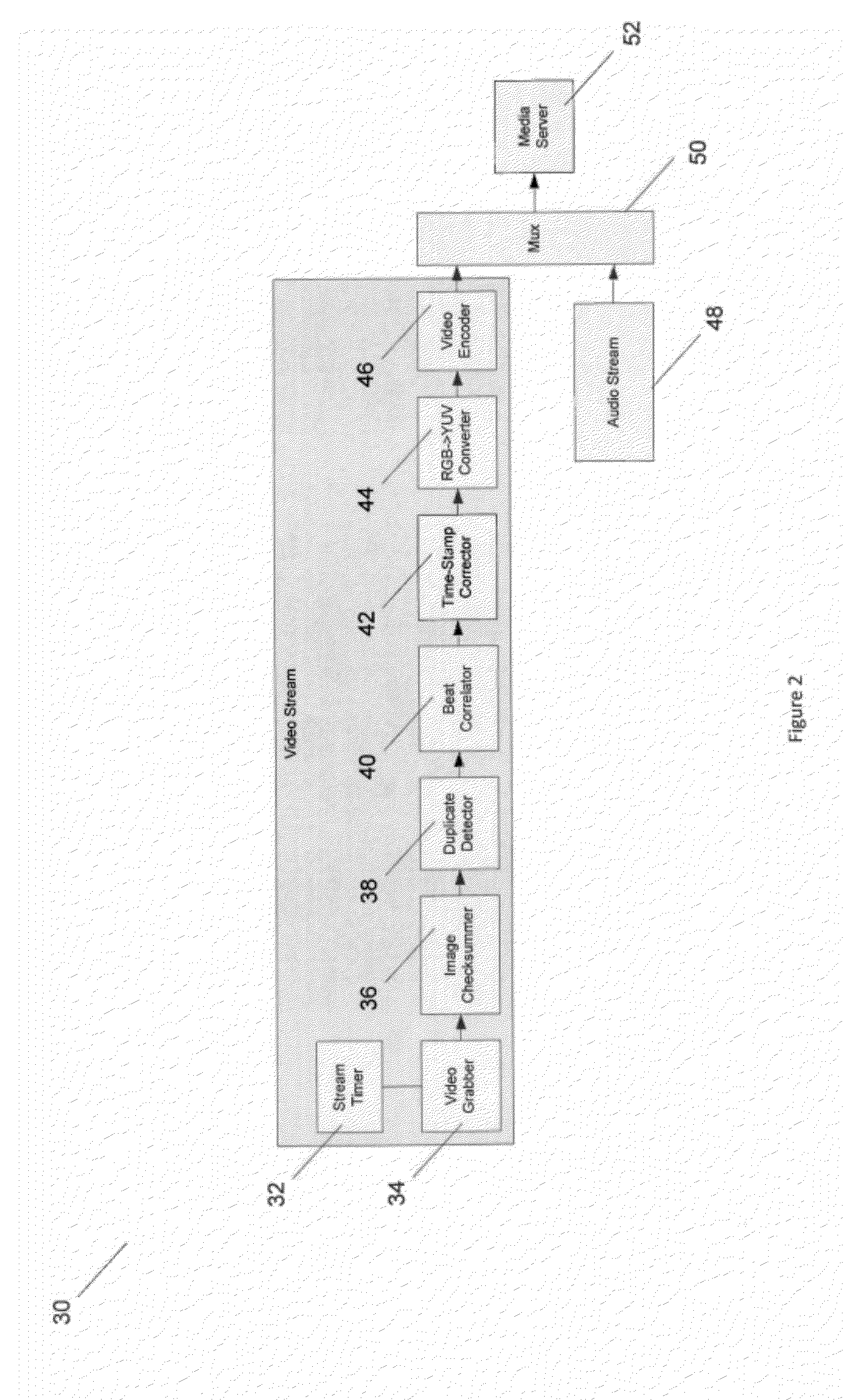
[0010]It is desirable to ensure that such a method works well on a wide range of PCs with different CPU and
graphics performance and so methods of minimise resource overhead are important. In addition to addressing judder, the advent of
high resolution images and videos, operating at resolutions such as 720p, 1080i and 1080p, means that
image quality is also becoming more and more important to users and so methods of allowing such
high definition footage to be processed on a wide performance range of PCs following capture is also important.
[0014]Autocorrelation enables the
fundamental frequency to be determined but further analysis may be needed to determine the location of the duplicated frames within the series of captured video frames. The method may therefore further comprise determining a beat cycle position of each of the identified duplicated frames. The beat cycle position defines a frame offset of each of the identified duplicated frames relative to a reference position within the same beat cycle as the particular identified duplicated frame (the beat cycle defines a series of capture frames between two successive identified duplicated frames occurring at the beat frequency). Dependent on the position of the identified duplicated frame within the beat cycle, the
flame may be deleted which assists in ensuring any false positives in the duplication detection are not unexpectedly deleted (for example owing to a series of frames where there is no change).
[0015]The reference position may be determined by a timing of a correlation peak of a correlation between a tracking
mask having a bit pattern period dependent on the beat frequency and the matching data. The bit pattern dependent on the beat frequency provides a tracking
mask with a bit pattern identifying frames only occurring at the beat frequency. The timing of correlation peaks then enables the position of the particular frames occurring at the beat frequency to be derived and thus also allows other frames, not occurring at the expected times, to not be marked for deletion. The reference position may also be defined in terms of frames, for example the
reference frame may be one of the successively identified duplicated frames which were detected occurring at the beat frequency and the timing / offset may be measured relative to this frame. Thus determining the beat cycle position of each of the identified duplicated frames may comprise cross correlating the matching data with data at the beat frequency.
[0016]The captured series of video frames may each comprise a presentation
timestamp defining a presentation time for each of the video frames. These presentation timestamps provide information including a time of display at the source frame rate. Consequently, the
retiming may comprise modifying the presentation timestamps of one or more of the filtered series of video frames (because some frames may have been deleted) to amend the presentation time of the remaining frames before presentation on the receiving device, such as a television display. This enables the juddering to be removed allowing a smoother
scrolling video to be rendered.
[0018]To identify duplicated frames in consecutive frames, corresponding portions of consecutive frames may be compared to determine if the corresponding portions match one another. This may be by comparing one large region of the video frame or alternatively may comprise dividing each portion into smaller regions such that the entire video flames are not compared and only smaller regions, or segments of the display, are compared. Comparing only selected portions of the video frames is less computationally expensive, allowing the comparison to be implemented on a broader performance range of computers. The regions may be dispersed over the video frame in order to detect movement in many different positions within the video frame, which may improve the probability of detecting a change in the image in each video frame. This may lead to a reduction in the number of frames incorrectly marked as a duplicate (false positives).
[0021]The video frames may be captured from
video memory on the host computer, which may be dedicated memory within a
graphics card or alternatively could be
shared memory, a portion of which is allocated to the display. The
video memory storing the images for displaying on the host computer may operate at a video
refresh rate, such as 60 Hz for example. Preferably the capturing is synchronised to this video
refresh rate in order to avoid tearing of images (whereby part of one frame and part of a subsequent frame are read from
video memory owing to a change of data in video memory during a capture cycle). Synchronising may be 1:1 synchronisation, or more preferably may be an integer division of the video
refresh rate, such as a half, or a third, or a quarter to reduce to overhead of capture.


