Radial counterflow muffler for no reduction and pollutant collection

a muffler and pollutant technology, applied in the field of mufflers, can solve the problems of increasing the heat and wear of the engine, reducing the fuel efficiency, and increasing the fuel requirements, and achieve the effect of effectively separateing pollutants

Active Publication Date: 2012-08-02
VORSANA INC
View PDF10 Cites 13 Cited by
  • Summary
  • Abstract
  • Description
  • Claims
  • Application Information

AI Technical Summary

Benefits of technology

[0020]A long residence time in the workspace effectively separates pollutants from the nitrogen ballast. Centrifugal separation occurs in vortices forced in the shear layer between the turbines, and multi-scale coherent structures in the shear

Problems solved by technology

Mufflers have been used to reduce the noise out of the exhaust pipe, but the mufflers do not capture the pollution in the exhaust stream, and reduce fuel efficiency by causing backpressure.
Backpressure due to this isotropic turbulence in the tortuous flow path means that the engine must work harder to push the exhaust through to discharge, raising the fuel requirements and increasing the heat and wear on the engine.
Because conventional muffler design obstructs flow, exhaust gas pulses cannot move fast enough to create low pressure wakes to evacuate the cylinders and accomplish exhaust pulse scavenging.
Natural gas internal combustion engines also have CO2 and NOx pollution.
Nitric oxide is thermodynamically unstable, so its reduction to

Method used


Image

  • Radial counterflow muffler for no reduction and pollutant collection
  • Radial counterflow muffler for no reduction and pollutant collection
  • Radial counterflow muffler for no reduction and pollutant collection

Examples


Embodiment Construction

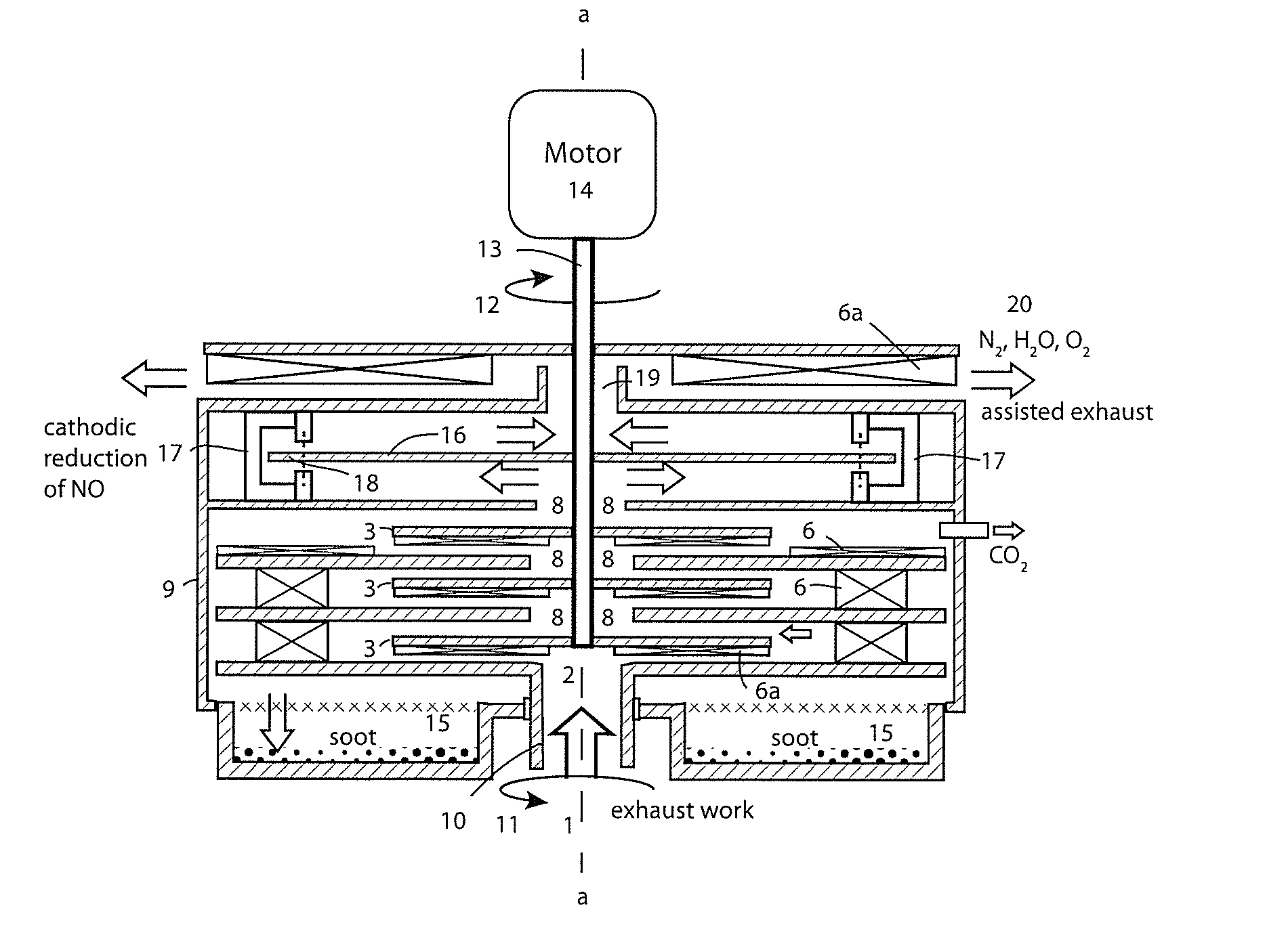
[0131]FIG. 1 shows a cross section of the left half of a single pair of counter-rotating radial turbines in the first stage of a cascade. An exhaust gas input stream 1 from an internal combustion engine enters through an axial feed port 2 which is at the center of a lower radial turbine 5. The input stream is partially blocked by a baffle 3, disposed between the axial feed port 2 at the center of the lower radial turbine 5 and an axial extraction port 8 at the center of the upper radial turbine 7. The vanes 6 on the disks can be radial turbine vanes that are actuated by a radially outward flow from the axis of rotation a-a through the workspace 4 between the radial turbines, or they may advect the outward flow when the disk is turned by suitable means, such as a motor. The term radial turbine herein refers to the combination of the disk and one or more vanes, whether the turbine advects or is advected by the flow through the workspace 4.

[0132]Each of the disks 5, 7 comprises an arra...


PUM

PropertyMeasurementUnit
Flow rateaaaaaaaaaa
Magnetic fieldaaaaaaaaaa
Acoustic propertiesaaaaaaaaaa

Abstract

A scrubbing muffler for internal combustion engines comprises coaxial counter-rotating disk pairs stacked in a cascade. Acoustic pulses are attenuated by doing work and dissipated by the circuitous path through the dynamic cascade. A motor and/or Venturi effect from slipstream over a vehicle assists exhaust and reduces backpressure for greater fuel economy. Exhaust gas fed at the axis is sheared between the disks of the first stage of the cascade as it passes radially outward into a shrouding tank disposed about the cascade. Vortex rebound at the tank wall advects flow radially inward back through the workspace between the first stage disks to axial extraction as feed for the second stage of the cascade. N2 and H2O, along with CO and NO, can pass radially inward to successive stages. Soot and CO2 stay in the tank. NO and CO are reduced at a Faraday disk cathode.

Description

APPLICATION HISTORY[0001]The applicants claim priority based on U.S. Provisional Application 61 / 438,596 filed Feb. 1, 2011.BACKGROUND[0002]1. Technical Field[0003]The present disclosure relates to mufflers and means for diminishing the noise and emissions of internal combustion engines such as catalytic converters and soot collectors. It also relates to electrolytic reduction of nitric oxide (NO) and to collection of soot and carbon dioxide from internal combustion engines.[0004]2. Prior Art[0005]Internal combustion engines produce exhaust streams which contain pollution and noise. Mufflers have been used to reduce the noise out of the exhaust pipe, but the mufflers do not capture the pollution in the exhaust stream, and reduce fuel efficiency by causing backpressure.[0006]Noise from internal combustion engines results from acoustic pulses of the engine exhaust stream. These acoustic exhaust pulses conventionally are dissipated by a muffler, which conventionally is a static device w...

Claims


Application Information

Patent Timeline
IPC IPC(8): F01N1/12B01D45/00B03C3/017B01D50/00C25B9/00
CPCF01N1/083F01N1/18F01N3/01F01N3/0892F01N5/04C25B9/125Y02T10/16Y02T10/20B01D53/326B01D2257/404F01N2240/34C25B9/30C25B11/034Y02T10/12
Inventor MCCUTCHEN, DAVID J.MCCUTCHEN, WILMOT H.
Owner VORSANA INC
Why Eureka
Try Eureka