Device for singulating and dispensing rigid and semi-rigid strips

a technology of rigid and semi-rigid strips and singulating, which is applied in the direction of instruments, apparatus for dispensing discrete articles, de-stacking articles, etc., can solve the problem of airborne contaminants infiltration potential

Active Publication Date: 2012-08-09
SAWA KEVIN G
View PDF5 Cites 21 Cited by
  • Summary
  • Abstract
  • Description
  • Claims
  • Application Information

AI Technical Summary

Benefits of technology

[0008]A principal object of the present invention is to provide a simple, inexpensive, reusable container device to singulate and dispense one at a time, rigid and semi-rigid strips such as test strips. A further object is to provide such a device to store and protect the integrity of a plurality of strips from outside moisture and contaminants, and which is transparent, thereby allowing the user to easily view the position, orientation and number of the strips contained within, to confirm the capture of a single strip to be dispensed, and to view the condition of a replaceable desiccant. After the strips are loaded they are not touched or exposed to outside contaminants until they are actually dispensed for use, one at a time.
[0010]The device of the invention does not differ significantly in size from a conventional test strip storage vial, and therefore may be conveniently stored in a standard diabetes test kit.
[0011]The invention is described in several embodiments. In each embodiment the device singulates the test strips by singulating, through rotation along its longitudinal axis, at least one test strip on the planar surface of the capture element. When the dispenser is tilted top cap down, the singulated test strip is then guided along the planar surface by the capture ridge toward and then through the devices aligned apertures. The apertures are typically 97% smaller than the open mouth of the conventional test strip vial. This, plus short open times greatly reduce the potential for the infiltration of airborne contaminants and moist ambient air into the container. This maintains the relative humidity inside the container at a more constant state, better preserving the integrity of the contents.
[0012]In one embodiment, the device is comprised of three molded parts, is easily assembled and other than the partially rotating top cap, has no moving parts. The transparent storage container allows the user to hold the dispenser in a generally horizontal position and, with visual cues, manipulate the dispenser to capture and confirm that a single test strip is on the capture element. The top cap is then rotated to align the inner and outer apertures. In use, the dispenser is tilted, top cap down to dispense the test strip by gravity through the aligned apertures. The top cap is then rotated back to the closed, sealed position.

Problems solved by technology

This, plus short open times greatly reduce the potential for the infiltration of airborne contaminants and moist ambient air into the container.

Method used


Image

  • Device for singulating and dispensing rigid and semi-rigid strips
  • Device for singulating and dispensing rigid and semi-rigid strips
  • Device for singulating and dispensing rigid and semi-rigid strips

Examples


first exemplary embodiment (figs.1 , 2 , 3 and 3a)

First Exemplary Embodiment (FIGS. 1, 2, 3 and 3A)

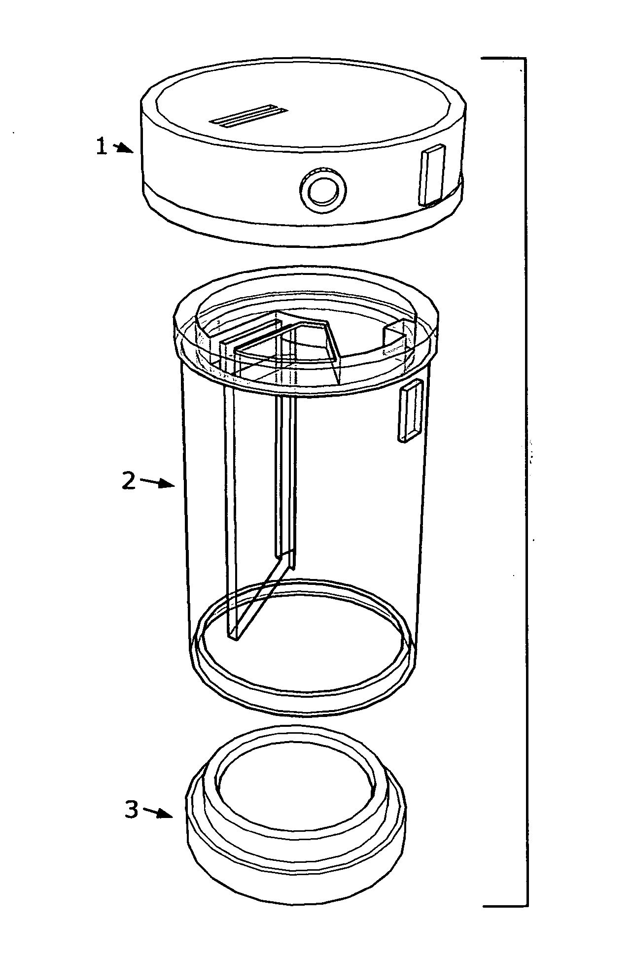
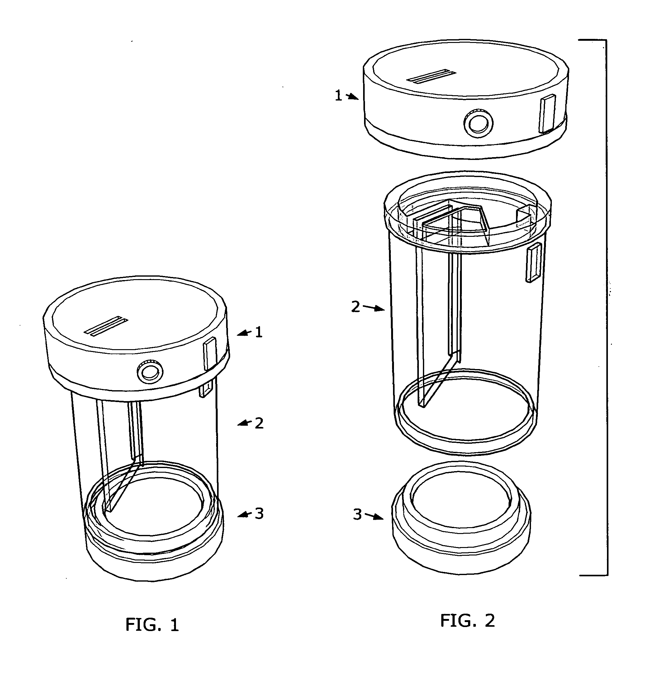
[0053]FIG. 1 shows an outside perspective view of the assembled first exemplary embodiment of the subject dispensers.

[0054]FIG. 2 shows an exploded perspective view of the dispenser in FIG. 1 with its constituent parts: a partially rotatable polymer top cap 1; a transparent polymer storage container 2; and a polymer base cap 3.

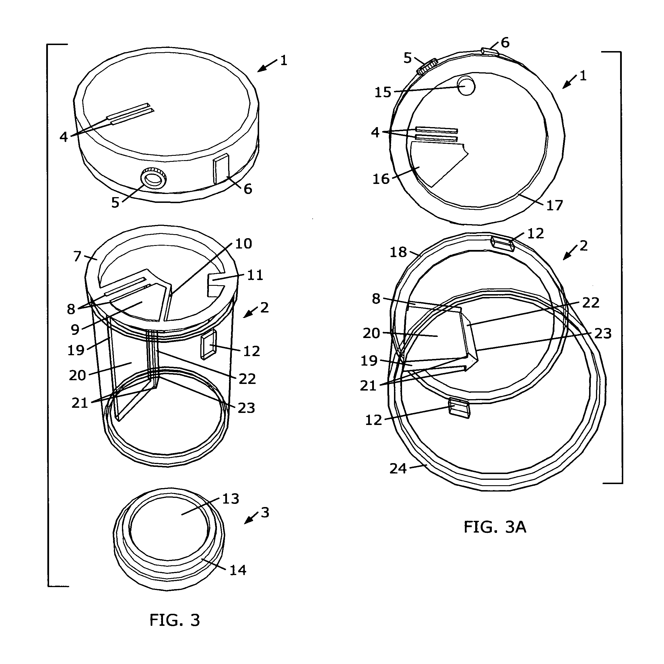
[0055]FIG. 3 shows details of the parts in FIG. 2 in an exploded, top perspective view. The top cap 1 is shown with its dual outer apertures (which can also be combined to form a single outer aperture) 4, and its closed 5 and open 6 status indicators. The outer apertures 4 may be sized slightly larger than the inner apertures 8 to insure unobstructed test strip dispensation.

[0056]The top of the storage container 2 is shown with the rotation bearing surface 7, dual inner apertures 8, the outer aperture sealing pad 9, the open rotation stop 10, and closed rotation stop lug 11. Also seen is one of the two top cap s...

second exemplary embodiment (figs.4 , 5 , 6 , 6a)

Second Exemplary Embodiment (FIGS. 4, 5, 6, 6A)

[0072]FIG. 4 shows an outside perspective view of the assembled second exemplary embodiment of the subject dispensers.

[0073]FIG. 5 shows an exploded perspective view of the dispenser in FIG. 4 with its constituent parts: a partially rotatable polymer top cap 1; an opaque polymer capture element insert 25; a transparent polymer storage tube 26; and a polymer base cap 3.

[0074]FIGS. 6 and 6A show details of the parts in FIG. 5. Only selected details of the insert 25 and the storage tube 26 will be described. Unless noted, all other components, features, details and methods are the same as described above in the first exemplary embodiment.

[0075]FIG. 6 shows the parts of FIG. 5 in an exploded perspective view. The top surface of the insert 25 is shown with the same details as the top surface of the storage container 2 described above in the first embodiment. The insert 25 has the capture element 19 from the first embodiment integrally molded...

third exemplary embodiment (figs.7 , 8 , 9 , 9a)

Third Exemplary Embodiment (FIGS. 7, 8, 9, 9A)

[0081]FIG. 7 shows an outside perspective view of the assembled third exemplary embodiment of the subject dispensers.

[0082]FIG. 8 shows an exploded perspective view of the dispenser in FIG. 7 with its constituent parts: a partially rotatable top cap 1; a spring 31; an opaque capture element insert 32; a transparent polymer storage tube 26; and a base cap with desiccant 3.

[0083]Referring to FIGS. 9 and 9A. This third embodiment has all of the details and features of the second embodiment. Accordingly, only three new elements, the spring 31, the spring flex support 33, and the spring engagement pin 34 will be discussed in detail. The top surface of the insert 32 has the same details and features as the insert in the second embodiment described above. This insert, however, has the addition of a raised, molded spring flex support 33. The spring flex support 33 works in conjunction with the rotation stop lug 11 to contain the base of the cant...


PUM


Abstract

A container device for storing, singulating and dispensing rigid and semi-rigid strips such as diagnostic test strips. A plurality of strips is contained and protected within a transparent container having an internal capture element for capturing and positioning a single strip adjacent a narrow normally-closed dispensing aperture. The aperture is exposed by rotating a spring-loaded container top cap to an open position. A detachable container base cap contains a desiccant and is replaceable. An optional stand stores the device in an upright position, and incorporates a tool to facilitate removal of the base cap for replenishing the container's contents or replacing the desiccant. A radio frequency identification (RFID) tag can be incorporated for electronic inventory control. The device can also be used as an integrated test strip container / single strip dispensing means for an automated analyte meter module.

Description

FIELD OF THE INVENTION[0001]The invention relates to containers for protecting and dispensing one at a time, rigid and semi-rigid strips such as diagnostic test strips.BACKGROUND OF THE INVENTION[0002]Rigid and semi-rigid strips, such as test strips are used extensively in chemical analysis and medicine. For example, test strips are used to check for chemical concentrations or contaminants in water chemistry. In medicine, diagnostic test strips are used to measure analyte concentrations in biological fluids. Diagnostic test strips are commonly used by diabetics to monitor their blood glucose levels.[0003]Such test strips are moisture sensitive and need to be protected from contaminants and maintained at appropriate humidity levels. They are usually stored in moisture resistant, polymer vials containing some sort of desiccant located in the cap or co-molded in the vial itself. Ideally, to avoid contamination, test strips should not be handled or touched before use.[0004]Some diabetic...

Claims


Application Information

Patent Timeline
Patent Type & Authority Applications(United States)
IPC IPC(8): B65D83/08B65G59/00A47F1/04
CPCG01N33/48757
Inventor SAWA, KEVIN G.
Owner SAWA KEVIN G
Why Eureka
Try Eureka