Method and system for treating a contaminated fluid

Inactive Publication Date: 2012-08-23
SANTORO ORONZO +5
View PDF8 Cites 31 Cited by
  • Summary
  • Abstract
  • Description
  • Claims
  • Application Information

AI Technical Summary

Benefits of technology

[0061]In another embodiment of the present invention, the treatment unit may be configured with at least one heating mechanism such as, but not limited to, microwaves, heating coils or super heated steam for heating the contaminated fluid in-conjunction with treating agents, to a predetermined temperature range, to achieve the rapid reaction kinetics such as, but not limited to, the ones of catalytic processes performed by treating agents to further improve the overall processing efficiency for treating the contaminated fluid.
[0062]In another embodiment of the present invention, the treatment unit may be configured with one or more high-frequency ultrasonic mechanisms to facilitate an integrated mixing of the contaminated fluid, and to achieve the rapid reaction kinetics such as, but not limited to, the ones of catalytic processes performed by treating agents to further substantially improve the overall processing efficiency for treating the contaminated fluid.
[0063]In another embodiment of the present invention, the treatment unit may be configured with an electromagnetic/electrostatic treatment mechanism for enhancing the processing rate of the contaminated fluid, as well as to facilitate the separation between the process residuals and the purified fluid.
[0064]In another

Problems solved by technology

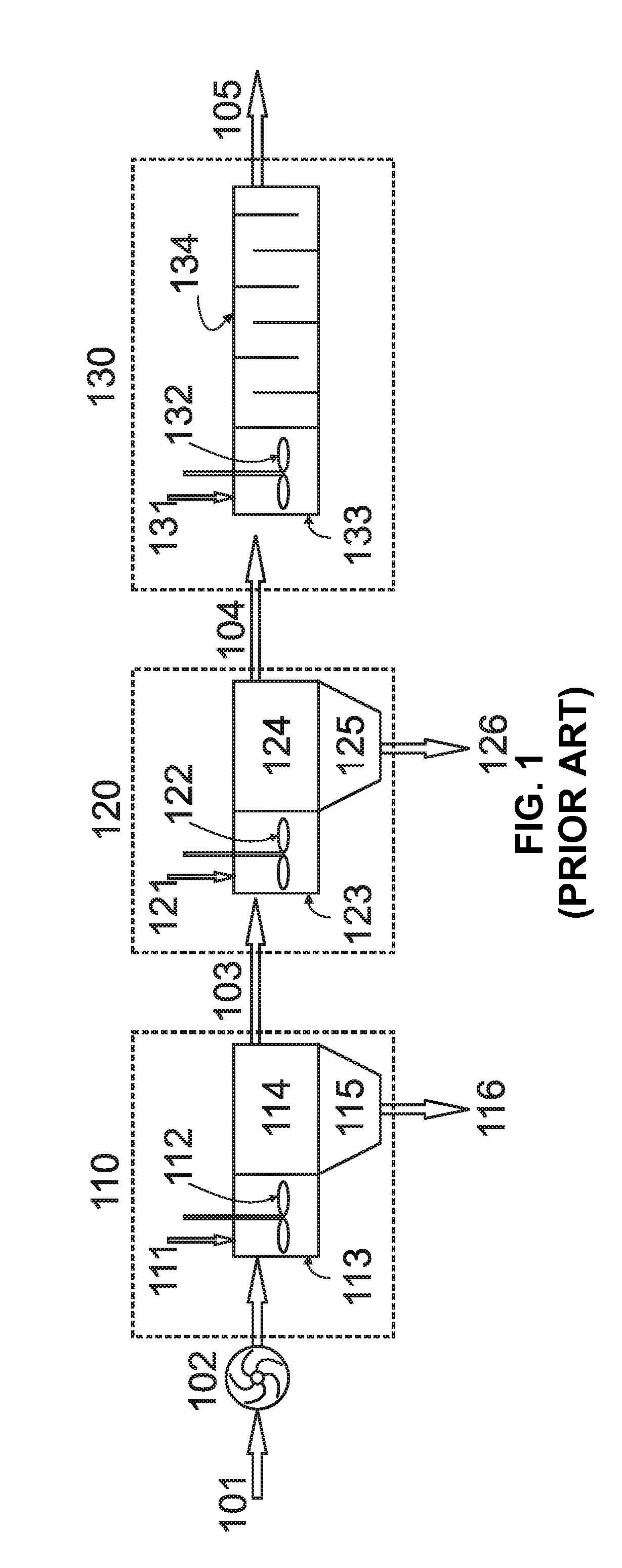
Even when simplified treatment schemes are considered (e.g. treatment schemes where some of the treatment stages shown in FIG. 1 are omitted), these processes are still energy and footprint intensive, as the stages requires specific pumps and mixers to move the fluid from one stage to the next as well as to effectively disperse the treating agents into the contaminated fluid in the various stages.
It is well documented the lack of mixing is responsible for diffusion-limited or incomplete reactions, known as one of the main causes of treatment inefficiency and undesired byproduct formation in chemical reactor engineering.
Therefore, proper rapid mixing leads to maximization of process efficiency and minimization of treatment time (and cost) for a given treatment objective.
Mixing and treatment operations often are complex and multi-faceted.
The use of such nozzles may generate substantial hydraulic head losses, and in many high flow-rate applications the hydraulic head losses are highly undesirable.
Since the generated shear rates in the elbow are not significantly high and typically are not considered to be highly anisotropic, this method tends to not produce a uniform mixture.
As a result of the many small ports in this system, the pressure drop is large and the system may not be ideal for accommodating large flow rates.
However, the injection means introduce the injected fluids into the fluid stream at once near the same location and do not enable fluids to be injected and mixed into the fluid stream in a prescribed sequence, and is helpful or needed in some fluid treatment systems.
This causes some of the fluids being injected to potentially escape through the inlet to contaminate the reservoir, and is unde

Method used


Image

  • Method and system for treating a contaminated fluid
  • Method and system for treating a contaminated fluid
  • Method and system for treating a contaminated fluid

Examples


Embodiment Construction

[0068]The present invention is best understood by reference to the detailed figures and description set forth herein.

[0069]Embodiments of the invention are discussed below with reference to the Figures. However, those skilled in the art will readily appreciate that the detailed description given herein with respect to these figures is for explanatory purposes as the invention extends beyond these limited embodiments. For example, it should be appreciated that those skilled in the art will, in light of the teachings of the present invention, recognize a multiplicity of alternate and suitable approaches, depending upon the needs of the particular application, to implement the functionality of any given detail described herein, beyond the particular implementation choices in the following embodiments described and shown. That is, there are numerous modifications and variations of the invention that are too numerous to be listed but that all fit within the scope of the invention. Also, ...


PUM

PropertyMeasurementUnit
Sizeaaaaaaaaaa
Volumeaaaaaaaaaa
Speedaaaaaaaaaa

Abstract

The present invention provides an integrated method and system for treating a contaminated fluid. The integrated system and method is configured to simultaneously perform multiple functions, for example, transportation, mixing, treatment and separation. The contaminated fluid and treating agents are pumped simultaneously into a processing tank and vigorously mixed by at least one pump-mixer. The at least one pump-mixer is configured to simultaneously perform combined functions such as fluid transportation, rapid and vigorous mixing and treatment. The rapid and vigorous mixing by at least one pump-mixer enhances the processing rates considerably. The contaminants and the disaggregated particles undergo treatment as a result of their reactions with the treating agents. The process residuals, usually in the form of sludge, are separated from the treated fluid. The separation system is also configured to simultaneously perform multiple functions.

Description

CROSS-REFERENCE TO RELATED APPLICATIONS[0001]The present Utility patent application claims priority benefit of the U.S. provisional application for patent Ser. No. 61 / 444,115 entitled “INTEGRATED FLUID TREATMENT SYSTEM”, filed on 17, Feb. 2011, under 35 U.S.C. 119(e). The contents of this related provisional application are incorporated herein by reference for all purposes to the extent that such subject matter is not inconsistent herewith or limiting hereof.FEDERALLY SPONSORED RESEARCH OR DEVELOPMENT[0002]Not applicable.REFERENCE TO SEQUENCE LISTING, A TABLE, OR A COMPUTER LISTING APPENDIX[0003]Not applicable.COPYRIGHT NOTICE[0004]A portion of the disclosure of this patent document contains material that is subject to copyright protection. The copyright owner has no objection to the facsimile reproduction by anyone of the patent document or patent disclosure as it appears in the Patent and Trademark Office, patent file or records, but otherwise reserves all copyright rights whatsoe...

Claims


Application Information

Patent Timeline
IPC IPC(8): C02F1/28B01D21/02C02F1/52C02F1/72C02F1/00C02F1/36B01F25/64
CPCB01F5/0473C02F1/48B01F13/1022C02F1/001C02F1/008C02F1/28C02F1/281C02F1/283C02F1/36C02F1/52C02F1/5209C02F1/5236C02F1/72C02F1/722C02F1/725C02F1/76C02F1/78C02F9/00C02F2001/007C02F2301/024C02F2301/066C02F2303/04B01F5/16B01F25/3141B01F25/64B01F33/813
Inventor SANTORO, ORONZOPASTORE, TIZIANOMOGHADDAMI, MOSTAFARAISEE, MEHRDADCRAPULLI, FERDINANDOSANTORO, DOMENICO
Owner SANTORO ORONZO
Why Eureka
Try Eureka