Marking control device, laser application device, marking control method, and computer-readable recording medium having marking control program

Inactive Publication Date: 2012-08-23
RICOH KK
View PDF4 Cites 23 Cited by
  • Summary
  • Abstract
  • Description
  • Claims
  • Application Information

AI Technical Summary

Benefits of technology

[0047]Embodiments of the present invention provide a marking control device, a laser application device, a marking control method, a marking control program, and a recording medium embodying such a marking control program that solve or reduce one or more problems caused by the limitations and disadvantages of the related art. Specifically, a marking control devic

Problems solved by technology

The erasing failure may result from thermal decomposition of the developer, because the thermally decomposed developer is resistant to cohesion or crystallization and thus the thermally decomposed developer may not be easily separated from the leuco dye.
For example, when adjacent first and second lines are marked, the residual heat of the first line initially marked may interfere with the heating of the second line while the second line is being marked.
This interference may result in decoloration of the recording in the thermoreversible recording media.
However, if the thermoreversible recording medium contains an RF-ID tag, the thermoreversible recording medium has an increased thickness and thus is less flexible.
Further, if printing and erasure are repeated in such a contact recording/erasing process, the recording medium obtains an uneven surface due to ablation.
In this case; however, excessive heat is applied to curved portions of the loop or convolution so that the repeated durability of image formation in the thermoreversible recording medium is lowered.
Thus, in the related art technologies, there may be few image recording technologies capable of printing with high printing quality and high repeated durability of image formation, and recording an image on a medium in a short time; or there may be few image erasing technologies capable of uniformly applying heat to the recording medium, acquiring a wide erasing width of the medium, and erasing the recorded image in a short time.
However, with a thermal rewritable medium, simply scanning plural lines in parallel may not ach

Method used


Image

  • Marking control device, laser application device, marking control method, and computer-readable recording medium having marking control program
  • Marking control device, laser application device, marking control method, and computer-readable recording medium having marking control program
  • Marking control device, laser application device, marking control method, and computer-readable recording medium having marking control program

Examples


first embodiment

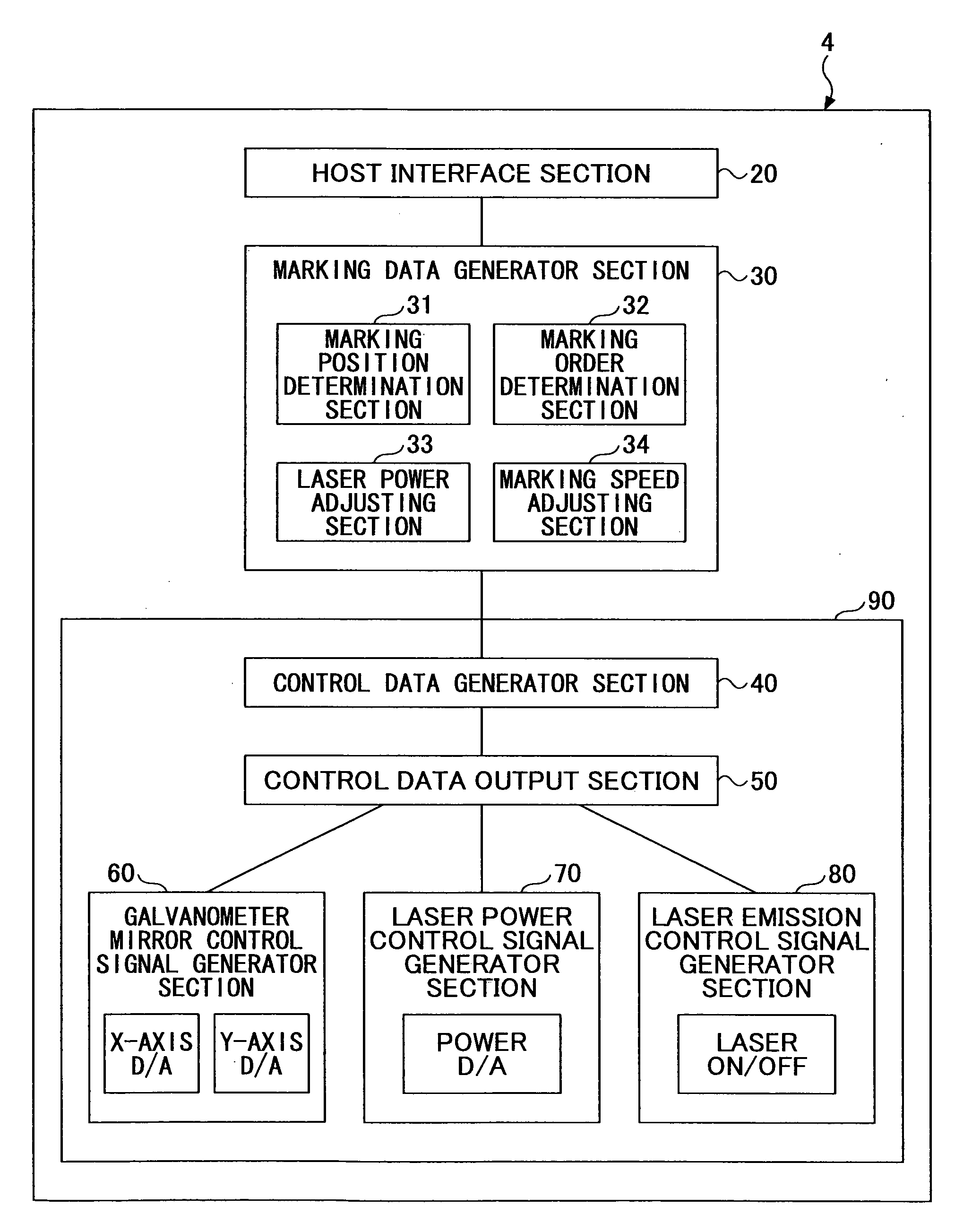
[0091]FIG. 6 is a configuration diagram illustrating a laser application device 1 according to a first embodiment. The laser application device 1 according to the first embodiment includes a laser device 2 configured to emit a laser beam, a scanner device 3 configured to scan the laser beam emitted from the laser device 2 onto the thermoreversible rewritable medium 100, and a marking control device 4 configured to drive control components of the laser application device 1.

[0092]The laser application device 1 scans the laser beam on the rewritable medium 100 based on marking instructions received from an external host computer 200 to mark a target image on the rewritable medium 100. The laser device 2 is configured to emit a laser beam based on an instruction received from the marking control device 4. The laser device 2 may be a semiconductor laser (i.e., a laser diode, LD) device, a YAG laser device, or a carbon dioxide gas laser device; however, the semiconductor laser (i.e., a la...

second embodiment

[0152]FIG. 14 is a configuration block diagram illustrating a marking control device 204 according to a second embodiment.

[0153]The marking control device 204 according to the second embodiment differs from the marking control device 4 according to the first embodiment in that the marking data generator section 30 of the marking control device 204 according to the second embodiment includes a marking position alteration section 235. Since the components of the marking control device 204 according to the second embodiment other than marking the position alteration section 235 are the same as those of the marking control device 4 according to the first embodiment, their descriptions are omitted by assigning the same reference numerals to the components same as those of the marking control device 4 according to the first embodiment.

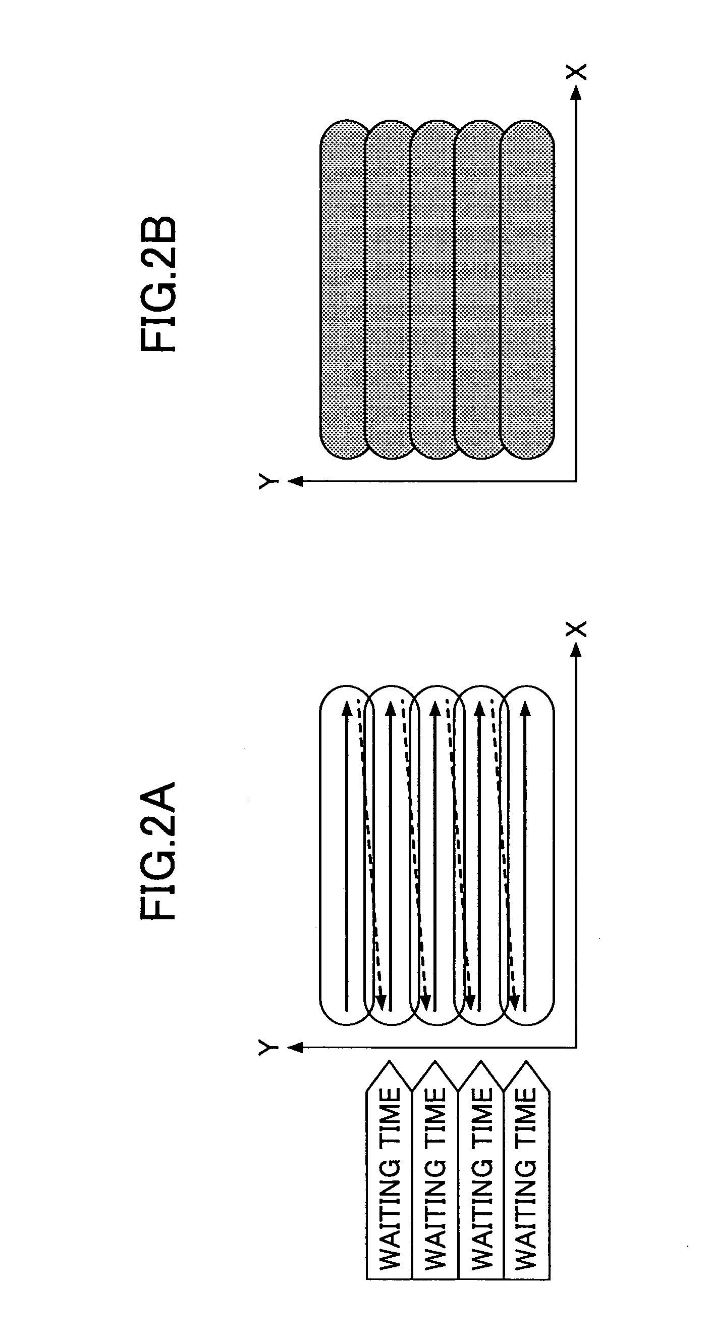
[0154]FIGS. 15A, 15B, 15C are diagrams each illustrating a marking method based on marking data generated by the marking control device 204 according to the...

manufacturing example 1

Manufacture of Thermoreversible Recording Medium

[0366]A thermoreversible recording medium capable of reversibly changing its color with applied heat was manufactured as follows.

—Supporting Member—

[0367]A white polyester film having a thickness of 125 μm (Tetoron Film U2L98W; manufactured by Teijin DuPont Films Japan Limited) was used as a supporting member.

—Forming of First Thermoreversible Recording Medium—

[0368]Five parts by mass of a reversible developer represented by the structural formula (1), 0.5 parts by mass of a first decoloring accelerator represented by the structural formula (2), 0.5 parts by mass of a second decoloring accelerator represented by the structural formula (3), 10 parts by mass of a solution containing 50 mass % acrylic polyol (hydroxyl value=200 mgKOH / g), and 80 parts by mass of methyl ethyl ketone were ground and dispersed by a ball mill until they had a mean particle size of approximately 1 μm.

[0369]Next, one part by mass of 2-anilino-3-methyl-6-dibutyla...


PUM

PropertyMeasurementUnit
Wavelengthaaaaaaaaaa
Timeaaaaaaaaaa
Timeaaaaaaaaaa

Abstract

A disclosed marking control device controls a marking device to mark a target image on a thermoreversible recording medium by applying a laser beam includes a marking position determination unit dividing the image into plural marking lines, and determining their marking positions; a marking order determination unit determining a marking order to mark the marking lines in mutually opposite directions; an adjusting unit adjusting a distance between a first ending point and a second starting point to be longer than a distance between a first starting point and a second ending point, or adjusting laser power applied to a second starting point side of the second marking line to be lower than the laser power applied to a second ending point side of the second marking line; and a marking instruction generator unit generating marking instructions including the marking positions of the marking lines and the marking order thereof.

Description

TECHNICAL FIELD[0001]A certain aspect of the present invention relates to a marking control device, a laser application device, a marking control method, and a computer-readable recording medium embodying a marking control program.BACKGROUND ART[0002]Commercially available laser application devices (also called “laser markers” or “laser marking devices”) are developed based on a technology where characters, numbers, and symbols are thermally recorded on a medium such as a thermosensitive paper by the application of laser beams.[0003]A laser beam emitted from a laser light source of the laser application device is applied to media such as plastic or thermosensitive paper, such that characters, symbols, etc., are recorded on such media. Examples of the laser light source include a gas laser, a solid-state laser, a liquid laser, and a semiconductor laser (i.e., a laser diode, LD).[0004]With metallic or plastic media, heat generated upon the application of a laser beam engraves or singe...

Claims


Application Information

Patent Timeline
IPC IPC(8): B41J2/47
CPCB41J2/4753G06K1/126B41M5/34G06K15/1228G06K15/029B41J2/32B41M5/284
Inventor YAMAMOTO, KAZUTAKAISHIMI, TOMOMIKAWAHARA, SHINYAASAI, TOSHIAKIHOTTA, YOSHIHIKO
Owner RICOH KK
Why Eureka
Try Eureka