
Electrosurgical generator controller for regulation of electrosurgical generator output power

a generator controller and electrosurgical technology, applied in the field of electrosurgical generator controller for controlling the output power of electrosurgical generators, can solve the problems of uncontrolled power excursions, unintended arcs, and large power excursions of current sources, and achieve accurate power source output characteristics, reduce power loss, and reduce the effect of power loss

Active Publication Date: 2012-08-23
UNIV OF COLORADO THE REGENTS OF +1
View PDF2 Cites 66 Cited by
  • Summary
  • Abstract
  • Description
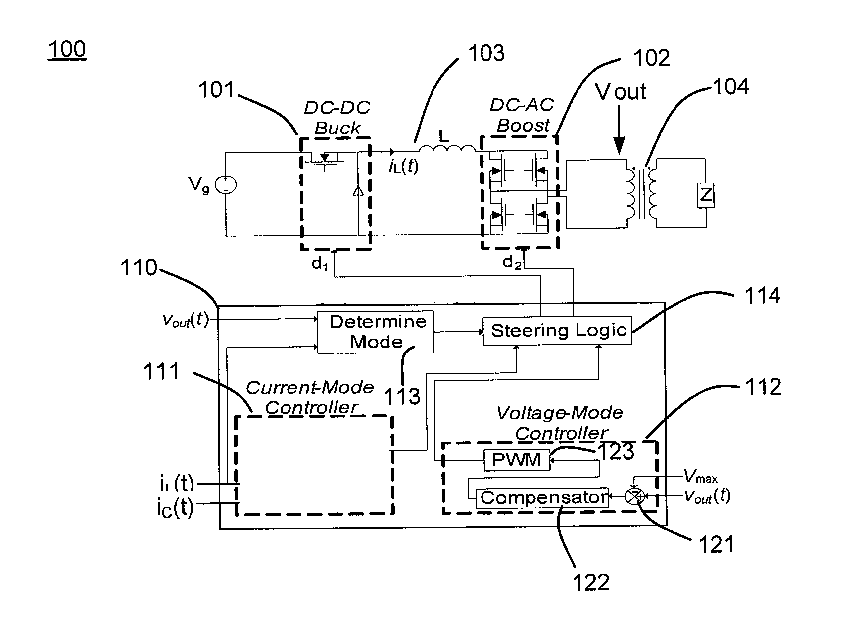
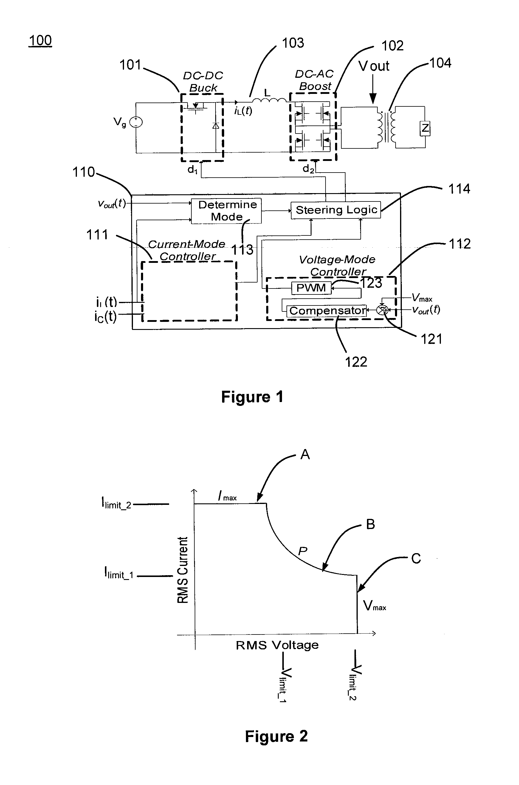
  • Claims
  • Application Information

AI Technical Summary

Benefits of technology

[0006]Using a high frequency inverter to form an arc between the output of an electrosurgical generator and tissue of a patient, a surgeon can induce joule heating in the affected cells; this causes the desired surgical effects of cutting, coagulation, and dissection. In an exemplary embodiment, the electrosurgery utilizes joule heating produced by the electrosurgical generator. The electrosurgical generator produces an accurate power source output characteristic, to which maximum voltage and current limits are added. The voltage and current limits of the electrosurgical generator contribute to the safety of the process. Furthermore, in an exemplary embodiment the voltage and current limits are configured to produce particular tissue effects which may be desirable in various surgical applications.
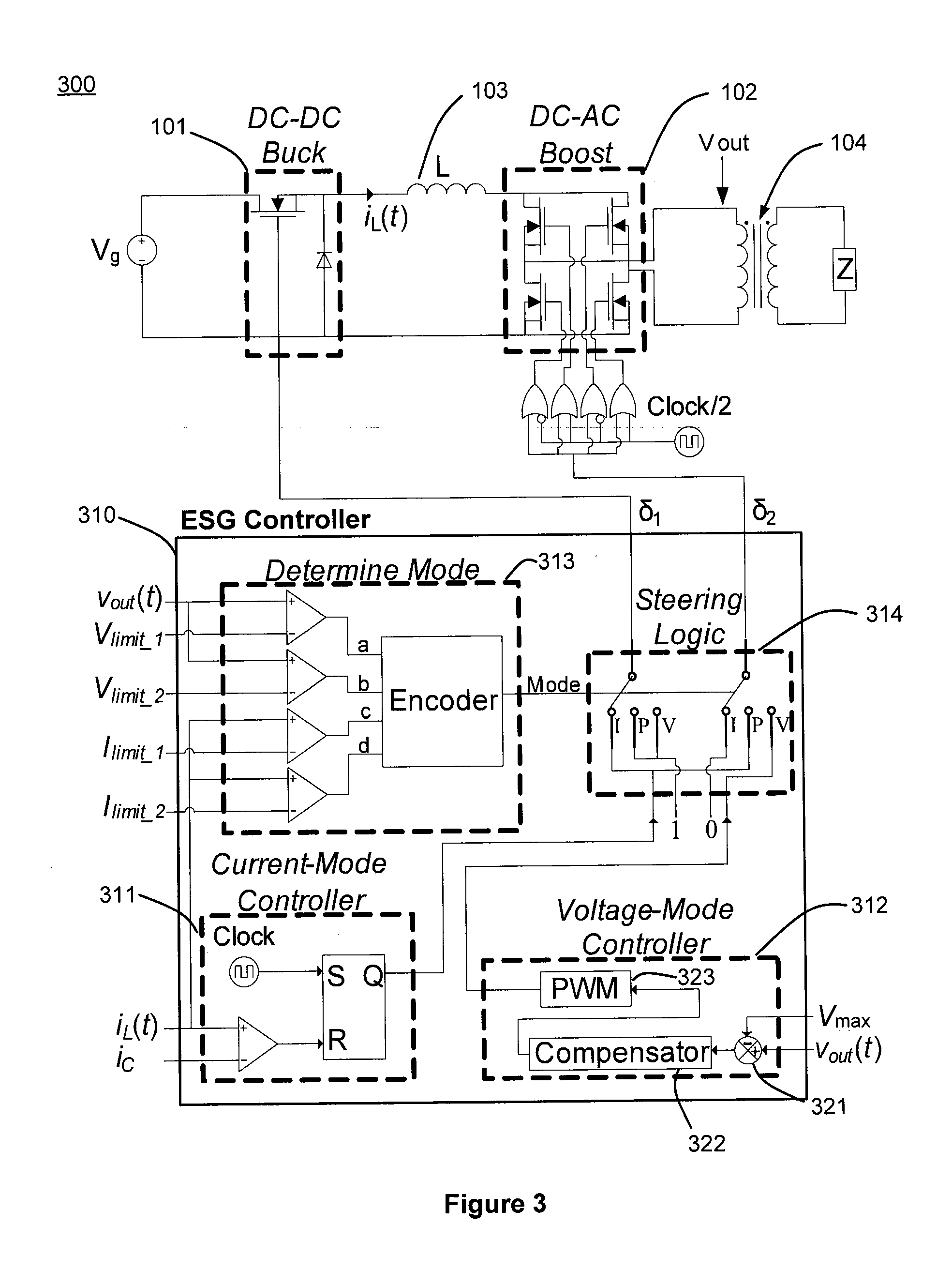
[0007]In an exemplary embodiment, an electrosurgical generator control system produces constant power output without measuring output voltage or output current, and regulates the output power with substantially deadbeat control. The electrosurgical generator control system performs near deadbeat control by regulating inductor current to a specified value, equal to a reference current. Thus, in an exemplary embodiment, the electrosurgical generator control system achieves a desired inverter output characteristic with an efficient and substantially deadbeat control method for AC output power. Furthermore, an exemplary electrosurgical generator control system switches between operating modes based in part on at least one of a measured output voltage, a measured inductor current, and by observing a duty cycle command generated by the control system. Additionally, an exemplary control system provides the ability to adjust the voltage and current limits and facilitate precision control of desired tissue effects. The desired tissue effects may include at least one of cut depth and the amount of surface hemostatis versus thermal spread.
[0008]Compared to prior art electrosurgical generators, an exemplary electrosurgical generator reduces unintended tissue damage by improving regulation of output power. In accordance with an exemplary embodiment, an electrosurgical generator controls the power during a cycle, and reacts to a change in power if arcing occurs. Voltage sources, especially, demonstrate the tendency to have large, uncontrolled power excursions during normal electrosurgical use. The magnitude of the power excursions may be dependent on various factors. One factor is how far the surgeon is away from the tissue when an arc occurs in the sinusoidal cycle. Furthermore, in the prior art, the current sources may introduce long, unintended arcs, even if distance from the tissue was well controlled. Therefore, in an exemplary embodiment, the electrosurgical generator may be configured to control power within a carrier frequency cycle for full arc and plasma control throughout the cycle. Power control within the duration of a carrier frequency cycle is advantageous over the prior art systems because arcing occurs faster than typical voltage or current detection feedback mechanisms can respond.
[0009]Furthermore, the exemplary electrosurgical generator is less complex than prior art electrosurgical generators. Moreover, it is an objective of this application to present an inverter topology and control algorithm which combines current-mode and voltage-mode control to realize the desired output characteristic of an electrosurgical generator in a markedly simpler and more accurate fashion. By directing which of two conversion stages is to be current-mode controlled, constant power, constant current, and constant voltage outputs can be achieved with excellent regulation and fast transitions.
[0010]In an exemplary embodiment, effective regulation of an electrosurgical generator's output is important to achieving the desired clinical effects. If output power is allowed to exceed the desired value, excessive thermal spread may occur, unnecessarily damaging and scarring tissue and impeding healing. If maximum output voltage exceeds the limiting value, charring of tissue may occur, which is frequently undesirable as it may unnecessarily damage tissue and obscure the surgical field. Use of an exemplary electrosurgical generator control scheme in an electrosurgical generator can provide near-deadbeat regulation of output power. In addition, the electrosurgical generator control scheme tends to assure that thermal spread is minimized by accurately supplying the specified power within a few cycles. Additionally, in various embodiments, fast and accurate regulation provided by the constant voltage mode minimizes unintentional tissue charring. Thus, reduced thermal spread and charring should result in better surgical outcomes by reducing scarring and decreasing healing times.

Problems solved by technology

Voltage sources, especially, demonstrate the tendency to have large, uncontrolled power excursions during normal electrosurgical use.
Furthermore, in the prior art, the current sources may introduce long, unintended arcs, even if distance from the tissue was well controlled.

Method used


Image

  • Electrosurgical generator controller for regulation of electrosurgical generator output power
  • Electrosurgical generator controller for regulation of electrosurgical generator output power
  • Electrosurgical generator controller for regulation of electrosurgical generator output power

Examples


Embodiment Construction

[0022]While exemplary embodiments are described herein in sufficient detail to enable those skilled in the art to practice the invention, it should be understood that other embodiments may be realized and that logical electrical and mechanical changes may be made without departing from the spirit and scope of the invention. Thus, the following detailed description is presented for purposes of illustration only.

[0023]In accordance with an exemplary embodiment, an electrosurgical generator controller operates with near-deadbeat control to maintain a desired AC output of an electrosurgical generator, which operates in at least one of a constant voltage mode, a constant current mode, and a constant power mode. The mode selection is generally based on the impedance associated with the tissue being cut. Different types of tissue, such as muscle and fat, have different impedances. In terms of electrosurgical operations, constant power output tends to uniformly vaporize tissue, resulting in...


PUM


Abstract

An electrosurgical generator may reduce unintended tissue damage by improving regulation of output power. The electrosurgical generator may control the power during a cycle, and react to a change in power if arcing occurs. Voltage sources, especially, demonstrate the tendency to have large, uncontrolled power excursions during normal electrosurgical use. The magnitude of the power excursions may be dependent on various factors. An exemplary electrosurgical generator control scheme reduces or minimizes the thermal spread by accurately supplying the specified power within a few cycles. Additionally, fast and accurate regulation provided by the constant voltage mode reduces or minimizes unintentional tissue charring. Thus, reduced thermal spread and charring should result in better surgical outcomes by reducing scarring and decreasing healing times. An electrosurgical generator controller may be configured to control both a DC-DC buck converter and a DC-AC boost inverter based in part on electrical parameters of the electrosurgical generator.

Description

CROSS-REFERENCE TO RELATED APPLICATIONS[0001]This application is a non-provisional of U.S. Provisional Application No. 61 / 426,985, entitled “DUAL CURRENT-MODE CONTROLLER FOR REGULATION OF ELECTROSURGICAL GENERATOR OUTPUT POWER,” which was filed on Dec. 23, 2010. This application is also a non-provisional of U.S. Provisional Application No. 61 / 530,528, entitled “CONSTANT POWER SOURCE BY NONLINEAR CARRIER-CONTROL OF A BUCK CONVERTER FOR USE IN AN ELECTROSURGICAL GENERATOR,” which was filed on Sep. 2, 2011. All of the contents of the previously identified applications are hereby incorporated by reference for any purpose in their entirety.BACKGROUND OF THE INVENTION[0002]An electrosurgical generator is commonly used in surgical practice to perform arc cutting and coagulation. The electrosurgical generator produces a high-frequency electric current to cut tissue with limited blood loss and enhanced cutting control compared to a metal blade. Standard industry practice is for electrosurgic...

Claims


Application Information

Patent Timeline
IPC IPC(8): A61B18/00H02M1/00H02M7/5387
CPCA61B18/1206A61B2018/00678A61B2018/00726H02M2001/007A61B2018/00827A61B2018/00892H02M7/53871A61B2018/00779H02M1/007A61B2018/00607A61B2018/00648A61B2018/0069A61B2018/0072A61B2018/00767A61B2018/00875A61B2018/1266A61B2018/1286
Inventor FRIEDRICHS, DANIELERICKSON, ROBERTGILBERT, JAMES
Owner UNIV OF COLORADO THE REGENTS OF
Learn More