Novel cracking catalytic compositions

a catalytic composition and composition technology, applied in the field of new cracking catalytic compositions, can solve the problems of loss of hydrocarbon materials, adverse effects on the composition of product mixes, and high conversion rates, and achieve the effects of maximizing conversion, minimizing aromatic formation, and maximizing the yield of lco

Inactive Publication Date: 2012-09-06
ALBEMARLE NETHERLANDS BV
View PDF3 Cites 4 Cited by
  • Summary
  • Abstract
  • Description
  • Claims
  • Application Information

AI Technical Summary

Benefits of technology

[0020]Yet another aspect of the present invention is a two-stage cracking process. In the first stage cracking conditions are set to minimize the formation of aromatics and maximize the yield of LCO. In the second stage bottoms conversion is maximized. The net effect will be a high yield of low aromatics LCO. The process set-up is very flexible, by changing operating conditions the unit can be changed from maximum distillate mode to maximum gasoline+LPG mode.
[0021]The catalyst used can be above-mentioned conventional standard acidic zeolite, such as Y-zeolite or a stabilized form of a Y-zeolite, containing FCC catalysts. Preferably, the Y-zeolite is combined with a matrix material, which may be alumina or silica-alumina. Optionally the catalyst may further comprise components for improving its resistance against poisoning by metal contaminants of the feedstock, in particular nickel and vanadium. Other components may be present to capture sulfur from the feedstock. This conventional catalyst is characterized by high cracking activity and promotes hydrogen transfer causing aromatic formation in the gasoline and LCO boiling range.

Problems solved by technology
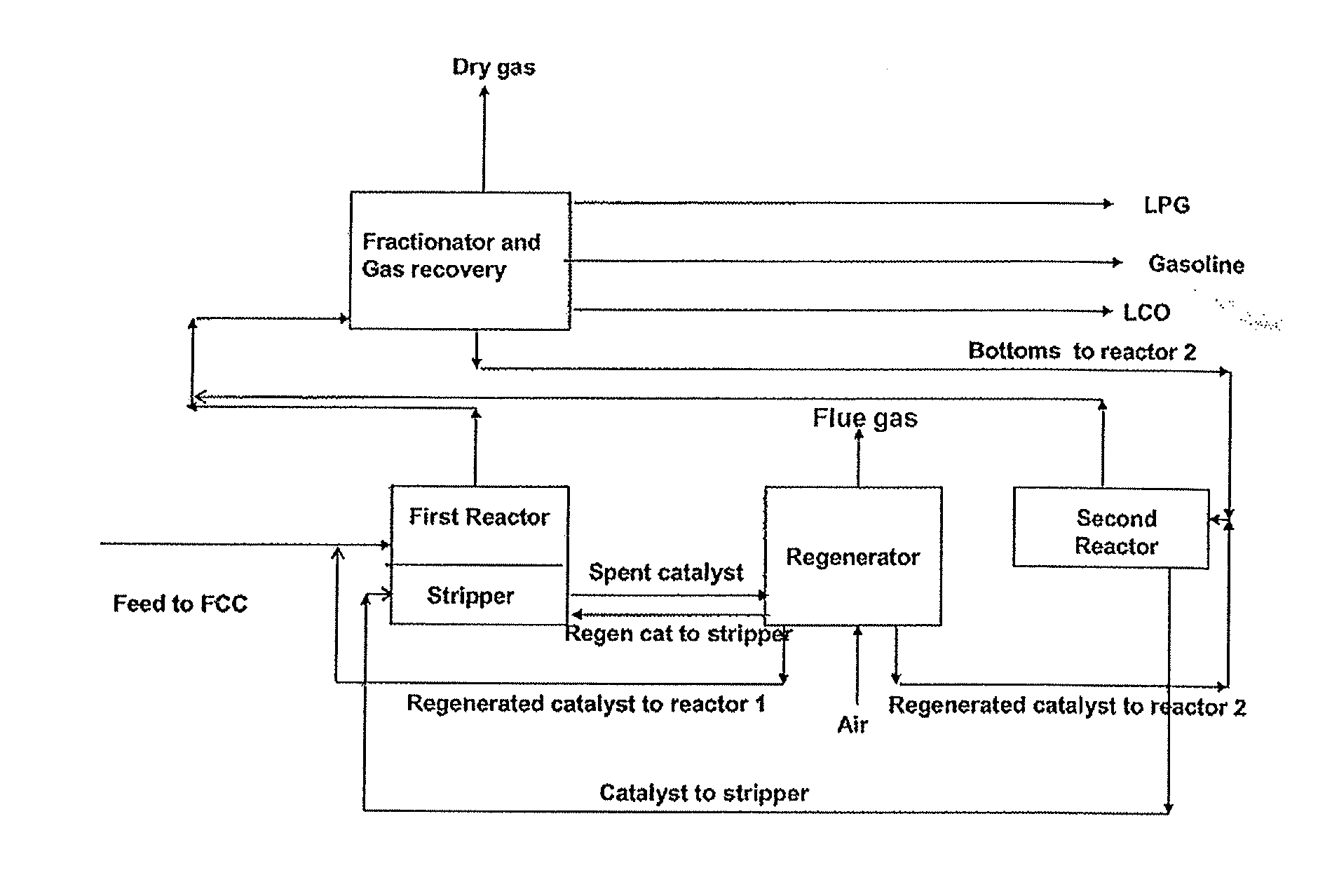
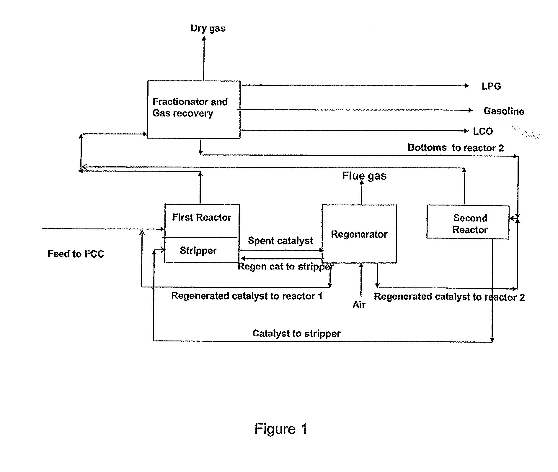
The product fraction having a boiling point above 340° C. is referred to as “bottoms.” Although it is desirable to operate at the highest possible conversion, the composition of the product mix is adversely affected by operating at high conversion rates.
A high coke yield is, however, undesirable, because it results in a loss of hydrocarbon material and disruption of the heat balance as burning off of the coke produces more heat than the process requires.

Method used


Image

  • Novel cracking catalytic compositions
  • Novel cracking catalytic compositions
  • Novel cracking catalytic compositions

Examples


example 1

[0084]The commercial FCC catalyst, a sample of the clay material, and a sample of the hydrotalcite material were tested in the test reactor described above. The feed conversion rate was varied by varying the catalyst-to-oil (CTO) ratio. For each test run the reaction product was collected. The LCO fraction was analyzed for aromatics content. Standard LCO cutpoint of 221 to 350° C. was used. The results are summarized in Table 1.

TABLE 1FCCFCCClayHTCCatalystClayHTCCatalystBottoms yield,303030202020wt %LCO Aromatics584258 (*)604570Content, wt %(*) estimate

[0085]Both the clay material and the hydrotalcite material produced an LCO fraction with significantly lower aromatics content than that produced by the conventional FCC catalyst.

[0086]Decreasing the bottoms yield by increasing the CTO ratio dramatically increased the aromatics content of the LCO fraction in the case of the conventional FCC catalyst. For example the aromatics content of LCO increased from 70 wt % to above 90 wt % when...

example 2

[0088]Aluminum phosphate materials prepared as described above were modified by impregnation with La, Zn, and Zr, respectively. Their properties are summarized in Table 3.

TABLE 3SA (ma / g)M (wt %)Al (wt %)P (wt %)AlPOx31613283LaAlPOx15629237ZnAlPOx20013381ZrAilOx12631155SA is the specific surface area, as measured by the BET method.M is the amount of dopant metal.Al is the amount of aluminum.P is the amount of phosphorus.

[0089]As feedstock Crown VGO was used.

CHARACTERISTICS OF KUWAIT VGOSIMDIST° C.10 wt %32020 wt %35330 wt %37440 wt %39350 wt %41460 wt %43770 wt %45780 w1 %47690 wt %51295 wt %FBP561SATURATES, wt %62.4MONO-AROMATICS, wt %17.0Di-AROMATICS, wt %11.1DI+-AROMATICS / POLARS, wt %9.4SULFUR, ppm wt6400NITROGEN, ppm wt1153CCR, wt %0.14

[0090]A silica magnesia material was prepared according to example 1 of U.S. Pat. No. 2,901,440, with the exception that no HF was added before drying.

[0091]The catalyst materials were tested for their cracking activities, as described in Example ...

example 3

[0096]Hydrotalcite was prepared following the procedure described in U.S. Pat. No. 6,589,902. The Mg to Al ratio was 4:1. The hydrotalcite was calcined at 600° C. for one hour. As desired, metal ions were impregnated into the hydrotalcite by rehydrating the calcined hydrotalcite in an aqueous solution containing a salt of the desired metal.

[0097]A hydrotalcite-type Zn / Al mixed oxide was prepared using the same procedure, but replacing Mg with Zn.

[0098]The materials were tested in a microactivity tester (MAT) as described above. The contact temperature was 500° C. The results are summarized in Table 5.

TABLE 5ZnAlMo1ZnAIW2ZnAlV3MgAIFeW4MgAlFeV5MgAIV6MgAlMo7MgAlW8MgAlP9MgAlZr10CTO11.1911.1811.1811.1811.1911.1811.1811.211.1811.18Gasoline17.1517.6817.0816.4715.6218.4916.7119.1117.8720.77LCO30.0133.4930.2930.6128.9632.3630.6633.9932.7132.50Bottoms315633.3025.0626.1023.6726.2726.2126.5831.3829.99Coke15.819.1721.0220.4325.4016.2119.0112.439.957.26LCO / arom42.4742.8743.8738.8739.5741.1041.803...


PUM

PropertyMeasurementUnit
temperatureaaaaaaaaaa
reaction temperatureaaaaaaaaaa

Abstract

Novel catalytic compositions for cracking of crude oil fractions are disclosed. The catalytic compositions comprise a basic material. When used in a cracking process, preferably a FCC process, the resulting LCO and HCO fractions have desirably low aromatics levels. Further disclosed is a one-stage FCC process using the catalytic composition of the invention. Also disclosed is a two-stage FCC process for maximizing the LCO yield.

Description

REFERENCE TO RELATED APPLICATIONS[0001]This Patent Application is a division of pending U.S. patent application Ser. No. 12 / 158,982, filed Dec. 8, 2008, which Application is the National Stage of International Patent Application No. PCT / EP2006 / 070204, filed on Dec. 22, 2006, which, in turn, claims the benefit of EP P Patent Application No. 05112841.1, filed Dec. 22, 2006, the disclosures of which are incorporated herein by reference.BACKGROUND OF THE INVENTION[0002]Crude oil is a complex mixture of hydrocarbons. In a refinery, crude oil is subjected to distillation processes to make a first separation by boiling point. One of the main fractions obtained in this process is Vacuum Gas Oil (VGO), which is commonly treated further in a cracking process, in particular a fluid catalytic cracking (FCC) process. Other feedstocks for cracking process include hydrotreated VGO and atmospheric resid.[0003]Cracking is the process by which the relatively large molecules in a feedstock such as VGO...

Claims


Application Information

Patent Timeline
Patent Type & Authority Applications(United States)
IPC IPC(8): C10G51/02C10G11/04C10G11/02C10G69/04C10G11/00
CPCB01J21/16B01J23/007B01J27/16B01J27/1804B01J27/1808B01J27/236C10G2400/02C10G2300/1033C10G2300/107C10G2300/1074C10G2300/1077C10G2300/4093C10G11/04C10G51/02B01J23/02B82Y30/00
Inventor O'CONNOR, PAULYUNG, KING YENCANOS, AVELINO CORMADE GRAAF, ELBERT ARJANRAUTIAINEN, ERJA PAIVI HELENA
Owner ALBEMARLE NETHERLANDS BV
Why Eureka
Try Eureka