
Instruments and interbody spinal implants enhancing disc space distraction

a technology of disc space and instruments, applied in the field of interbody spinal implants, can solve the problems of impaired discs, affecting the anatomical functions of vertebrae, and affecting the health of discs,

Active Publication Date: 2012-09-13
TITAN SPINE
View PDF6 Cites 52 Cited by
  • Summary
  • Abstract
  • Description
  • Claims
  • Application Information

AI Technical Summary

Benefits of technology

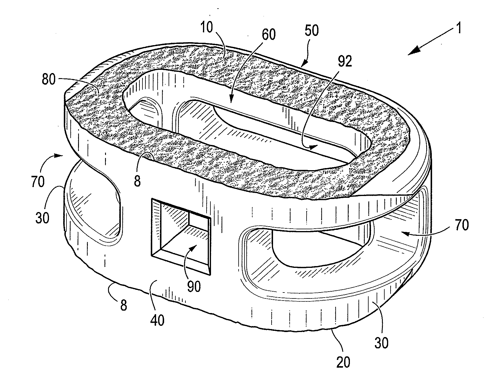
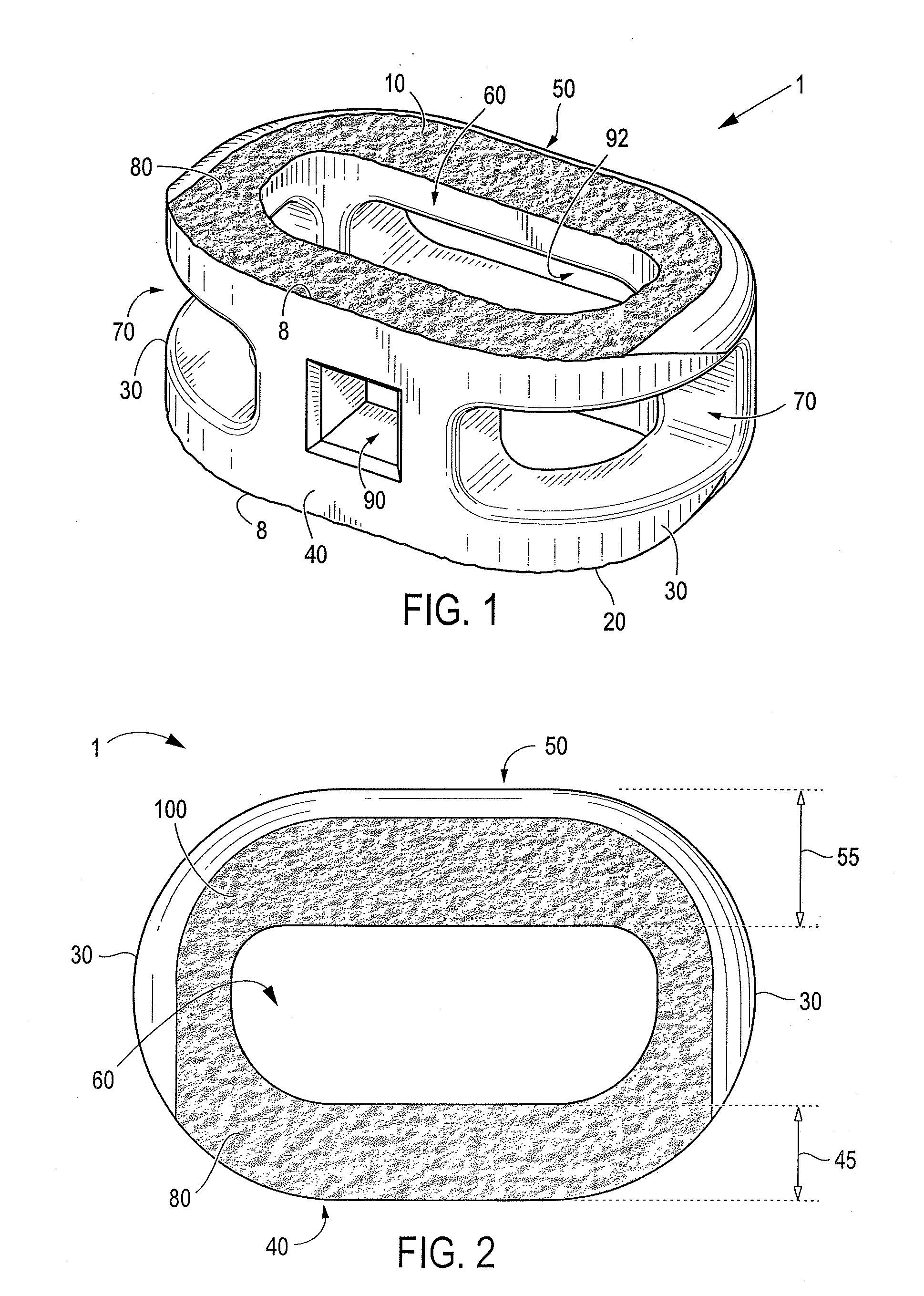
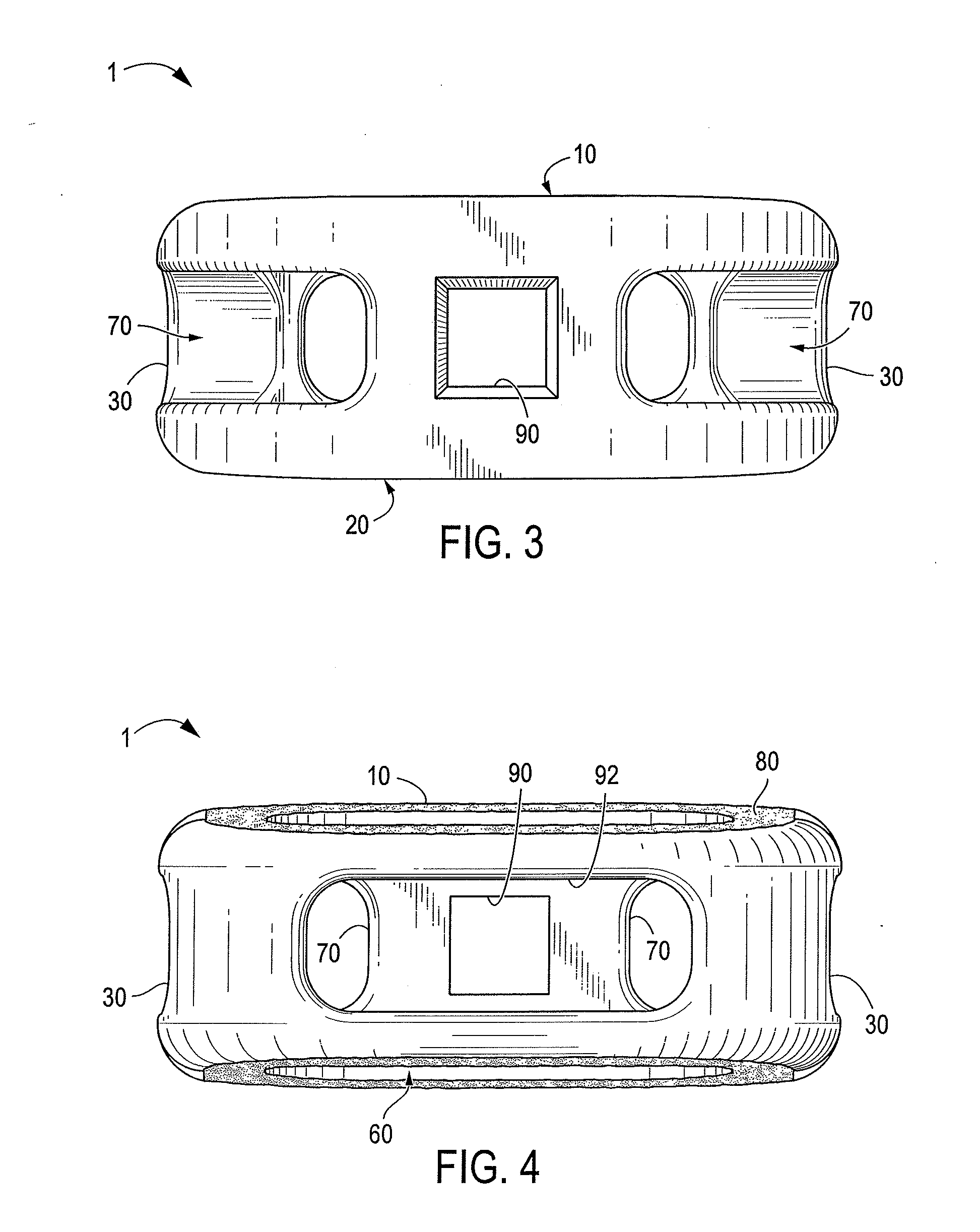
[0037]The present invention is directed to interbody spinal implants and to methods of using such implants. The implants can be inserted, using methods of the present invention, from a variety of vantages, including anterior, antero-lateral, and lateral implantation. Certain embodiments of the present invention provide an anatomically shaped spinal implant for improved seating in the disc space, particularly in the medial-lateral aspect of the disc space, and improved utilization of the vertebral apophyseal rim. Certain embodiments of the present invention further have a highly radiused posterior portion and sides which allow for ease of implantation. Thus, the posterior portion may have a generally blunt nosed profile. Certain embodiments also allow for improved visualization of the disc space during surgical procedures while minimizing exposure of the operating space. Certain aspects of the invention reduce the need for additional instrumentation—such as chisels, reamers, or other tools—to prepare the vertebral endplate, thus minimizing the instrument load upon the surgeon.
[0040]According to certain embodiments, the present invention provides an interbody spinal implant including a body having a top surface, a bottom surface, opposing lateral sides, opposing anterior and posterior portions, a substantially hollow center, and a single vertical aperture. The single vertical aperture extends from the top surface to the bottom surface, has a size and shape predetermined to maximize the surface area of the top surface and the bottom surface available proximate the anterior and posterior portions while maximizing both radiographic visualization and access to the substantially hollow center, and defines a transverse rim. The body may be non-metallic and may form one component of a composite implant; the other component is a metal plate disposed on at least one of the top and bottom surfaces of the body.

Problems solved by technology

Over time, the discs may become diseased or infected, may develop deformities such as tears or cracks, or may simply lose structural integrity (e.g., the discs may bulge or flatten).
Impaired discs can affect the anatomical functions of the vertebrae, due to the resultant lack of proper biomechanical support, and are often associated with chronic back pain.
This location is not the preferable seating position for an implant system, however, because only a relatively small portion of the vertebral endplate is contacted by these cylindrical implants.
The seating of these threaded cylindrical implants may also compromise biomechanical integrity by reducing the area in which to distribute mechanical forces, thus increasing the apparent stress experienced by both the implant and vertebrae.
Still further, a substantial risk of implant subsidence (defined as sinking or settling) into the softer cancellous bone of the vertebral body may arise from such improper seating.
Such allograft bone material restricts the usable size and shape of the resultant implant.
Therefore, these cages may not be of a sufficient size to contact the strong cortical bone, or apophyseal rim, of the vertebral endplate.
These size-limited implant systems may also poorly accommodate related instrumentation such as drivers, reamers, distractors, and the like.
For example, these implant systems may lack sufficient structural integrity to withstand repeated impact and may fracture during implantation.
Still further, other traditional non-allograft ring-shaped cage systems may be size-limited due to varied and complex supplemental implant instrumentation which may obstruct the disc space while requiring greater exposure of the operating space.
These supplemental implant instrumentation systems also generally increase the instrument load upon the surgeon.
Traditional interbody spinal implants generally do not seat properly on the preferred structural bone located near the apophyseal rim of the vertebral body, which is primarily composed of preferred dense subchondral bone.
Such challenges include: (1) end-plate preparation; (2) implant difficulty; (3) materials of construction; (4) implant expulsion; (5) implant subsidence; (6) insufficient room for bone graft; (7) stress shielding; (8) lack of implant incorporation with vertebral bone; (9) limitations on radiographic visualization; and (10) cost of manufacture and inventory.
In the process of aggressive end-plate removal, however, the end-plates are typically destroyed.
Such destruction means that the load-bearing implant is pressed against soft cancellous bone and the implant tends to subside.
The end-plates are concave; hence, if a flat implant is used, the implant is not very stable.
Even if a convex implant is used, it is very difficult to match the implant geometry with the end-plate geometry, as the end-plate geometry varies from patient-to-patient and on the extent of disease.
This method also violates the structure.
2. Implant Difficulty
Traditional anterior spinal fusion devices can also be difficult to implant.
These edges can bind to the surrounding soft tissue during implantation, creating surgical challenges.
If there is a restriction on the exposure size, then the maximum size of the implant available for use is correspondingly limited.
Still further, secondary instrumentation may sometimes over-distract the annulus, reducing the ability of the annulus to compress a relatively undersized implant.
A typical traditional implant has design features to accommodate only one or two of these approaches in a single implant, restricting intra-operative flexibility.
Materials such as PEEK or cadaver bone do not have the structural strength to withstand impact loads required during implantation and may fracture during implantation.
Cadaver bone carries with it the risk of disease transmission and raises shelf-life and storage issues.
In addition, there is a limited supply of donor bone and, even when available, cadaver bone inherently offers inconsistent properties due to its variability.
Finally, as mentioned above, cadaver bone has insufficient mechanical strength for clinical application.
Both options can create localized stress risers in the end-plates, increasing the chances of subsidence.
The challenge of preventing implant expulsion is especially acute for PEEK implants, because the material texture of PEEK is very smooth and “slippery.”
Subsidence of the implant is a complex issue and has been attributed to many factors.
These design restrictions do not leave much room for filling the bone graft material into cortical bone implants.
The exposure-driven limitations on implant size narrow the room left inside the implant geometry for bone grafting even for metal implants.
Typically, however, the stiffness of the implant material is much greater than the adjacent vertebral bone and takes up a majority of the mechanical loads, “shielding” the bone graft material from becoming mechanically loaded.
In most cases, the typical fusion implant is not able to incorporate with the vertebral bone, even years after implantation.
Such inability persists despite the use of a variety of different materials to construct the implants.
The application of such bio-active materials has been limited, however, for several reasons, including biocompatibility, structural strength, and lack of regulatory approval.
For implants made out of metal, the metal prevents adequate radiographic visualization of the bone graft.
Hence it is difficult to assess fusion, if it is to take place.
This requirement means that the manufacturer needs to carry a significant amount of inventory of implants.
Because there are so many different sizes of implants, there are setup costs involved in the manufacture of each different size.
The result is increased implant costs, which the manufacturers pass along to the end users by charging high prices for spinal fusion implants.

Method used


Image

  • Instruments and interbody spinal implants enhancing disc space distraction
  • Instruments and interbody spinal implants enhancing disc space distraction
  • Instruments and interbody spinal implants enhancing disc space distraction

Examples


Embodiment Construction

[0078]Certain embodiments of the present invention may be especially suited for placement between adjacent human vertebral bodies. The implants of the present invention may be used in procedures such as Anterior Lumbar Interbody Fusion (ALIF), Posterior Lumbar Interbody Fusion (PLIF), Transforaminal Lumbar Interbody Fusion (TLIF), and cervical fusion. Certain embodiments do not extend beyond the outer dimensions of the vertebral bodies.

[0079]The ability to achieve spinal fusion is directly related to the available vascular contact area over which fusion is desired, the quality and quantity of the fusion mass, and the stability of the interbody spinal implant. Interbody spinal implants, as now taught, allow for improved seating over or near the apophyseal rim of the vertebral body. Still further, interbody spinal implants, as now taught, better utilize this vital surface area over which fusion may occur and may better bear the considerable biomechanical loads presented through the sp...


PUM


Abstract

An apparatus for distracting a disc space having an annulus. The apparatus includes a spinal implant having a pre-determined size sufficient to balance frictional fit in the disc space and elongation of the annulus. The implant has a top surface, a bottom surface, opposing lateral sides, and opposing anterior and posterior portions defining a substantially hollow center and a single vertical aperture. At least one of the opposing anterior and posterior portions presents a substantially flat impact face including an opening with an instrument retention feature. The apparatus also includes a rasp, a plurality of distractors, and an instrument able to engage and manipulate the spinal implant, the rasp, and the plurality of distractors. The size-specific rasp is adapted to clear the disc space of all soft tissue and cartilage. The plurality of distractors have progressively increasing heights adapted to distract the disc space before use of the spinal implant.

Description

CROSS REFERENCE TO RELATED APPLICATIONS[0001]This application is a continuation-in-part of U.S. patent application Ser. No. 12 / 151,198, filed on May 5, 2008, and pending, which is a continuation-in-part of U.S. patent application Ser. No. 11 / 123,359, filed on May 6, 2005, and issued as U.S. Pat. No. 7,662,186. The contents of both prior applications are incorporated by reference into this document, in their entirety and for all purposes.TECHNICAL FIELD[0002]The present invention relates generally to interbody spinal implants and methods of using such implants and, more particularly, to instruments and interbody spinal implants useful in enhancing disc space distraction.BACKGROUND OF THE INVENTION[0003]In the simplest terms, the spine is a column made of vertebrae and discs. The vertebrae provide the support and structure of the spine while the spinal discs, located between the vertebrae, act as cushions or “shock absorbers.” These discs also contribute to the flexibility and motion ...

Claims


Application Information

Patent Timeline
IPC IPC(8): A61F2/44
CPCA61F2/30965A61B2017/922A61F2002/2817A61F2002/2835A61F2002/30014A61F2002/30133A61F2002/30405A61F2002/30604A61F2002/30772A61F2002/30785A61F2002/30836A61F2002/30892A61F2002/30906A61F2002/30925A61F2002/4475A61F2002/448A61F2002/4629A61F2220/0025A61F2310/00017A61F2310/00023A61F2/4611A61F2002/4623A61F2002/30973A61F2/4684A61F2002/30357A61F2002/30485A61F2002/30616A61F2002/30784A61F2002/30838A61F2002/30922A61F2002/30924A61F2002/30927A61F2002/3093A61F2310/00179A61F2/4465A61F2/4603A61F2002/30593
Inventor ULRICH, JR., PETER F.PATTERSON, CHAD J.
Owner TITAN SPINE
Learn More