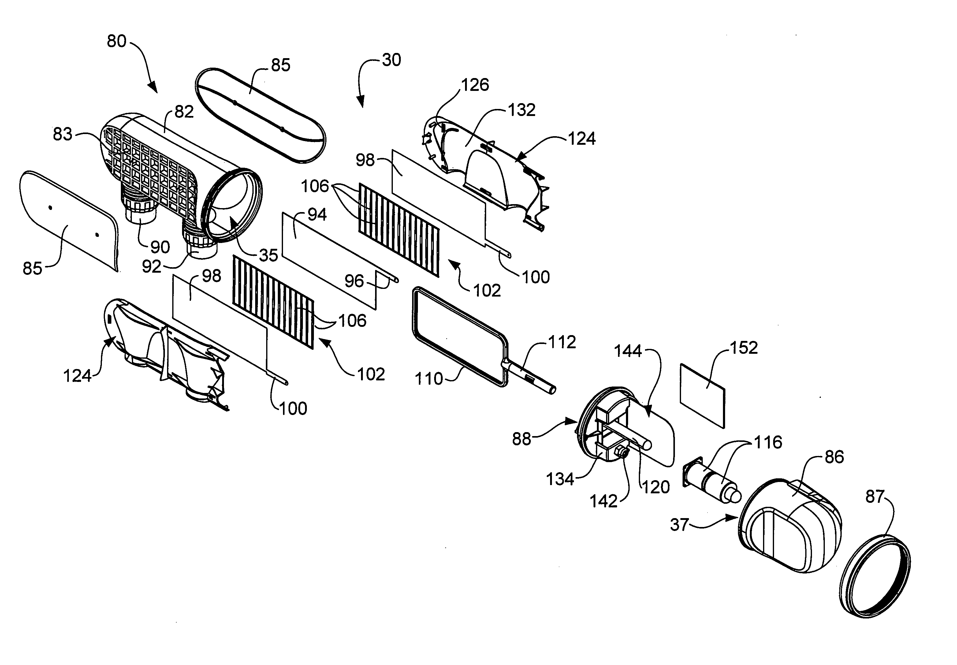
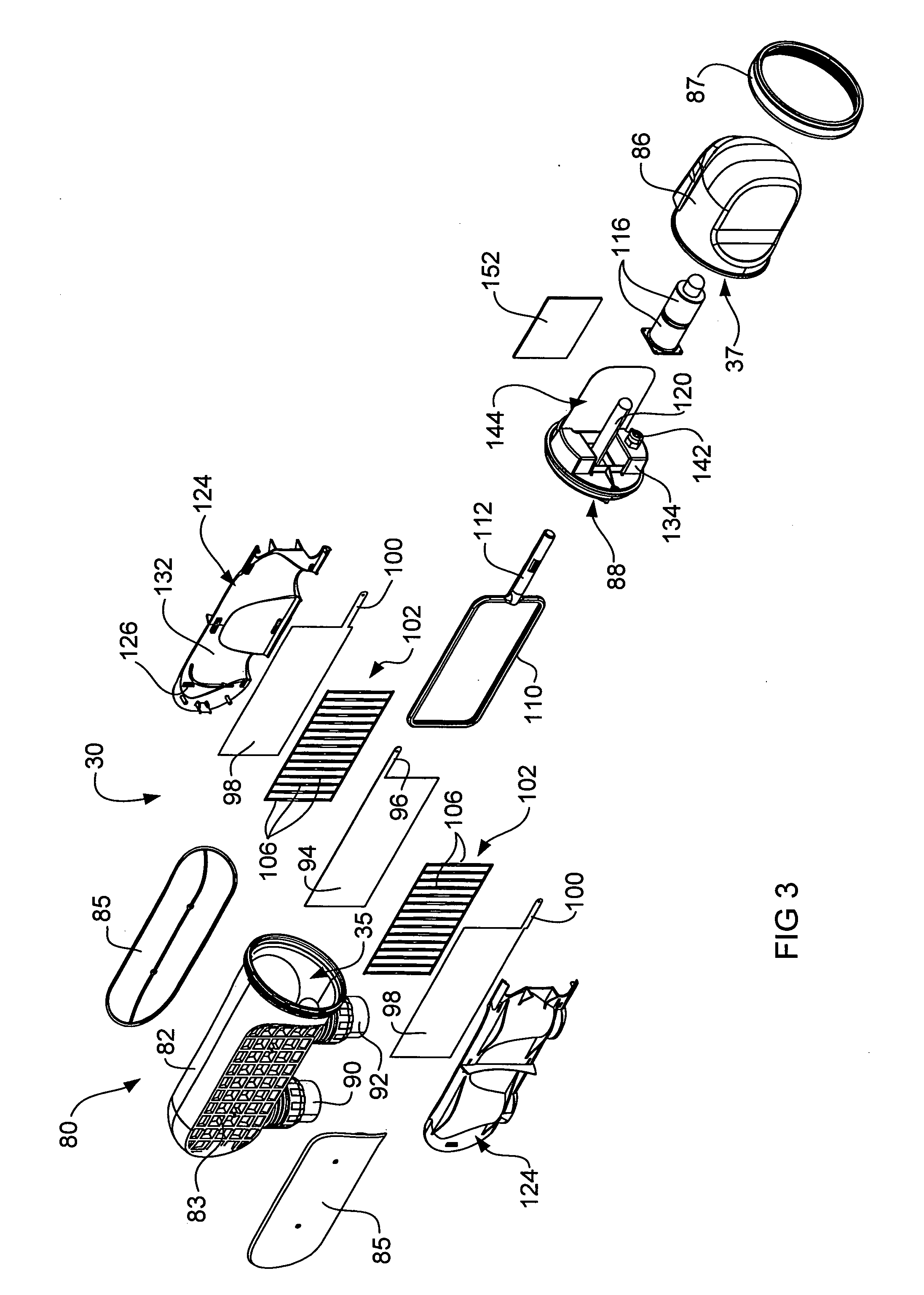
[0012]In embodiments where the cathode of the salt water chlorinator is a
plate electrode the scrapers may be substantially coextensive in
peripheral outline with the cathode. Also the scrapers are constructed to minimise “shading” of the cathode surface by the scraper. This is achieved by minimising the profile of the scrapers at right angles to the main surfaces of the cathode and
anode plates. Areas of the cathode shaded by the scrapers may not produce chlorine and thus by minimising the shading of the cathode surfaces by the scrapers,
chlorine production is maximised. Thus the or each scraper preferably has a mesh structure as above described (that is, a structure having opposite sides between which the scraping portions, being ribs, extend) such that shading of the adjacent cathode surfaces is minimised.
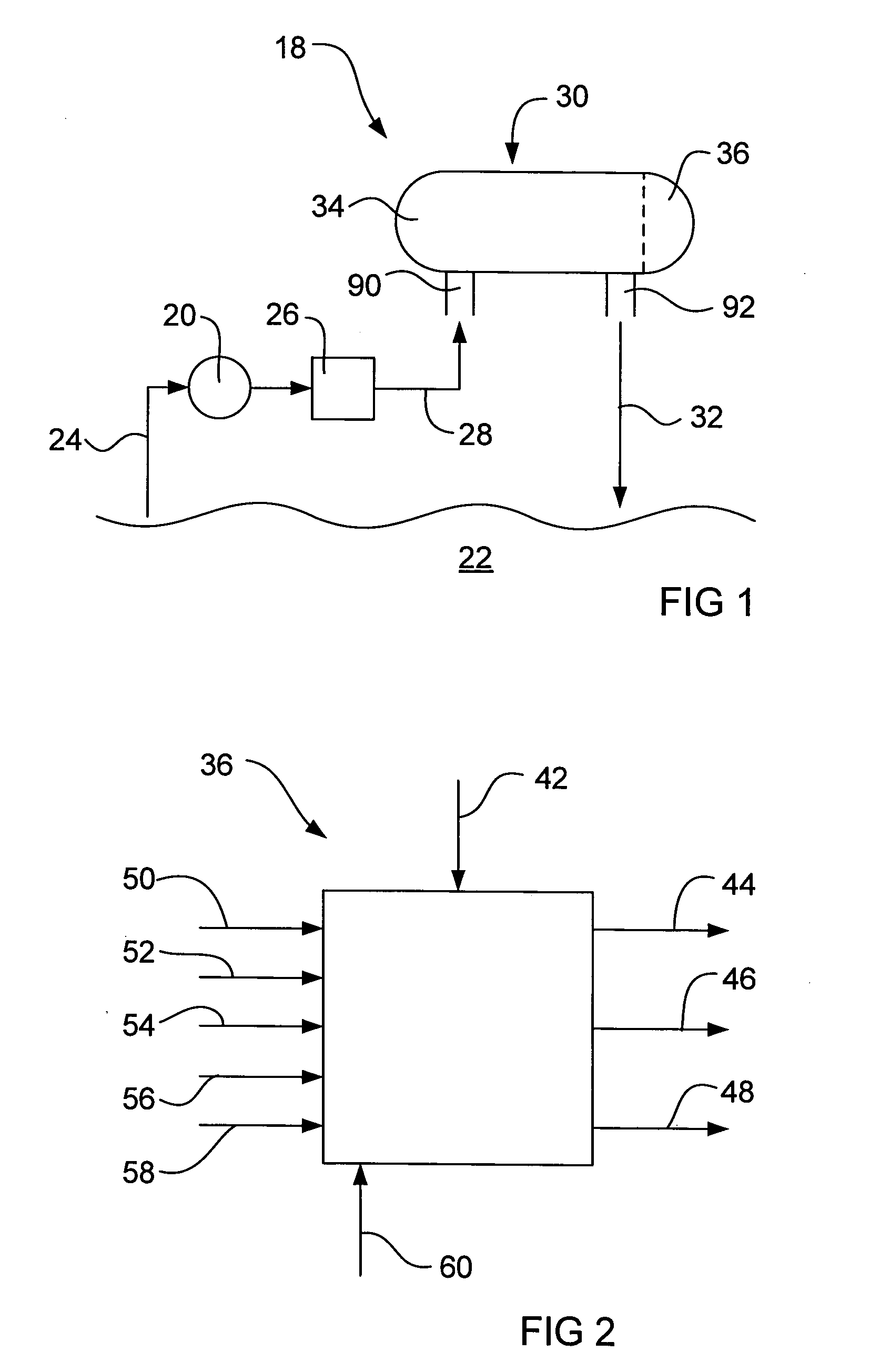
[0018]In an embodiment that includes a housing in which the housing defines two chambers, a
control circuit for the electrolysis cell is contained in the second chamber. The control circuit may include a flow sensor for sensing a flow of salt water through the electrolysis cell. This flow sensor can be operative to cause electrical power to the electrolysis cell to be switched off when there is no salt
water flow through the cell or if the flow rate does not exceed a predetermined minimum value. Thus this embodiment of the invention places a flow sensor within the housing to sense flow / no flow conditions in the electrolysis cell, in contrast for example to an exteriorly located flow sensor in the
piping to the electrolysis cell. Thus the flow sensor is located at the very location at which a safety problem may arise, for example if flow through the electrolysis cell ceases but electrical power continues to be supplied to the electrodes of the electrolysis cell, gases may be generated and contained in the electrolysis cell, and the pressure may increase sufficiently to cause an explosion if the electrolysis cell is isolated, for example if it has inlet and outlet valves which are closed. With this embodiment of the invention, when the flow through the electrolysis cell ceases, this is sensed by the flow sensor which, via the control circuit, switches off the power that is supplied to the electrodes of the electrolysis cell. This placement of the flow sensor within the chlorinator avoids a risk associated with a flow sensor that is associated with exteriorly located
piping which is that flow could still occur within the
piping but may not pass through the electrolysis cell (for example if the piping between the flow sensor and the electrolysis cell breaks). Alternatively, as mentioned above, if the flow rate falls below a predetermined minimum value, the power to the cell could be switched off Also, the salt water chlorinator, comprising principally an electrolysis cell and its control circuit, is provided as a single compact unit (that is, there is a single housing). This provides manufacturing advantages and therefore a less costly solution than many prior art installations where a control circuit and an electrolysis cell are provided as separate units. In this embodiment the housing preferably includes a wall element which divides the housing to provide the two chambers, and the wall element includes a region, which may be thinned compared to the thickness of the wall element, constituting an operative part of the flow sensor.
[0019]The flow sensor may include a heater (for example a resistance heater) and
two temperature responsive elements (for example thermistors) which are spaced apart, wherein the heater is for transferring heat into the salt water via said region of the wall element and the temperature responsive elements are for detecting differentials in the power required to maintain a first sensor (being one of the temperature responsive elements) adjacent to the heater at a higher temperature compared to a second
reference sensor (being the other of the
two temperature responsive elements) spaced away from the heater for detecting the presence or absence of a flow of salt water. The flow sensor enhances safety insofar as its immediacy to the actual flow of salt water through the electrolysis cell via said region of the wall element provides for sensing of a no flow condition and thus switching off of the power supply to the electrolysis cell before a damaging build up of pressure can occur.
[0020]The region of the wall element constituting an operative part of the flow sensor, which may be thinned, must be sufficiently strong to withstand pressures within the electrolysis cell. Consistent with this requirement, the thickness of the region is minimised (that is, it is thinned) for the
heat transfer through it to occur as quickly as possible to minimise delays in the
temperature sensing by the temperature responsive elements. This region is an operative part of the flow sensor due to its function in transferring heat from the heater into the salt water and from the salt water to the temperature responsive elements.
[0021]Using a region of the wall element, which is possibly thinned, for the flow sensor provides two advantages. Firstly, a suitable
polymer for the wall element is more
corrosion resistant than alternative wall element materials such as
metal, and secondly, there is no potential leak path between the control chamber and the chlorination chamber, thereby increasing reliability of the unit.
[0022]Preferably the reference temperature responsive element is also utilised for temperature detection within the electrolysis cell and componentry of the control circuit provides for
temperature measurement. Such temperature detection and measurement componentry may be operative to adjust power supply to the electrolysis cell and thus
chlorine production dependent upon detected temperatures, for example, production of chlorine at a temperature which is too high or too low could damage the electrolysis cell—thus temperature detection is used to stop or reduce
chlorine production if the detected temperature is at a possibly damaging value, being either too high or too low. Temperature detection can also be used between these limits to vary the output power of the cell to optimise chlorine production and maximise cell life.

