Extrusion press

a technology of a press and a press body is applied in the field of extrusion presses, which can solve the problems of large output electric servomotors, power consumption loss, and environmental pollution, and achieve the effects of reducing time and cost for maintenance and management, reducing power, and reducing nois

Inactive Publication Date: 2012-09-27
UBE MASCH CORP LTD
View PDF2 Cites 22 Cited by
  • Summary
  • Abstract
  • Description
  • Claims
  • Application Information

AI Technical Summary

Benefits of technology

[0024]The extrusion press of the present invention adopts the electric motor driven system, and therefore, an idling operation necessary for the hydraulic system is not necessary and it is possible to operate the motor only when each individual elemental device needs to be operated, and therefore, the effect of reducing power can be expected.
[0025]Since an electric motor is used as a drive source, it is only necessary to maintain the electric motor itself because the drive itself is the electric motor and the time and cost for maintenance and management are reduced because the number of parts to be maintained is smaller compared to that of a hydraulic source.
[0026]The leak of hydraulic oil does not occur and noise can be reduced, and therefore, the improvement of working environment is realized and the risk of fire can be avoided.
[0027]Further, controllability, such as positioning control, and operability are excellent.

Problems solved by technology

However, such a conventional extrusion press device uses hydraulic pressure as power (for example, see Patent Literature 1, Patent Literature 2), and therefore, there are problems with regard to the environment (noise, oil spill, etc.), energy saving (running cost), etc.
However, such a mechanism (ball screw and ball nut etc.) that converts rotational motion into rectilinear motion in place of a conventional hydraulic cylinder device capable of continuously outputting a large output capacity required for the extrusion press, for example, 9,800 kN (1,000 tf), or a large output electric servomotor is not realized.
The pump and motor and auxiliary pump and motor used for extrusion that utilize hydraulic equipment are always in the idling operation even when not necessary for the operation of the device directly, and therefore, power consumption loss occurs.
Further, when a machine user uses a machine for many years, the user needs to perform maintenance and inspection inevitably in order to maintain and manage the machine and it is considered that the time required for maintenance is by far longer in the case where the drive source is a hydraulic source than in the case where only an electric motor is used.
When the hydraulic equipment is used for many years, trouble, such as deterioration of the hydraulic oil, wear of valves, and oil spill from pipe connections, relates to many parts, such as pumps, valves, manifolds, and pipes, and therefore, it takes much time to troubleshoot the cause and take measures.
Further, when the hydraulic source is used, the hydraulic oil flows out (leak, discharge, etc.) at the time of maintenance, etc., and therefore, the machine operability and working environment deteriorate and there is a risk of fire because containers and dies are used in a high-temperature environment.
It is of course possible to use flame resistant hydraulic oil (water-glycol fluid etc.), however, ordinarily the hydraulic oil is used under high pressure in order to make the machine compact and the flame resistant hydraulic oil (water-glycol fluid etc.) is not suitable for use, and therefore, not normally used.
As described above, as the drawbacks of the conventional hydraulic drive system, there are problems as follows.
(1) The hydraulic oil is used as a medium, and therefore, it is difficult to realize accurate speeds and positions as in the case of the mechanical operation.
(2) The amount of energy consumption is comparatively large and cooling water is required to prevent the oil temperature from rising, and therefore, the running cost is increased.
(3) The number of components the circuit pressure of which is high is large and the noise during the operation is high.
(4) Since hydraulic oil is used, there exit problems of maintenance, environment, and cost resulting from leak of the hydraulic oil and problems of environment and cost accompanying the disposal of the hydraulic oil.

Method used


Image

  • Extrusion press
  • Extrusion press
  • Extrusion press

Examples


first embodiment

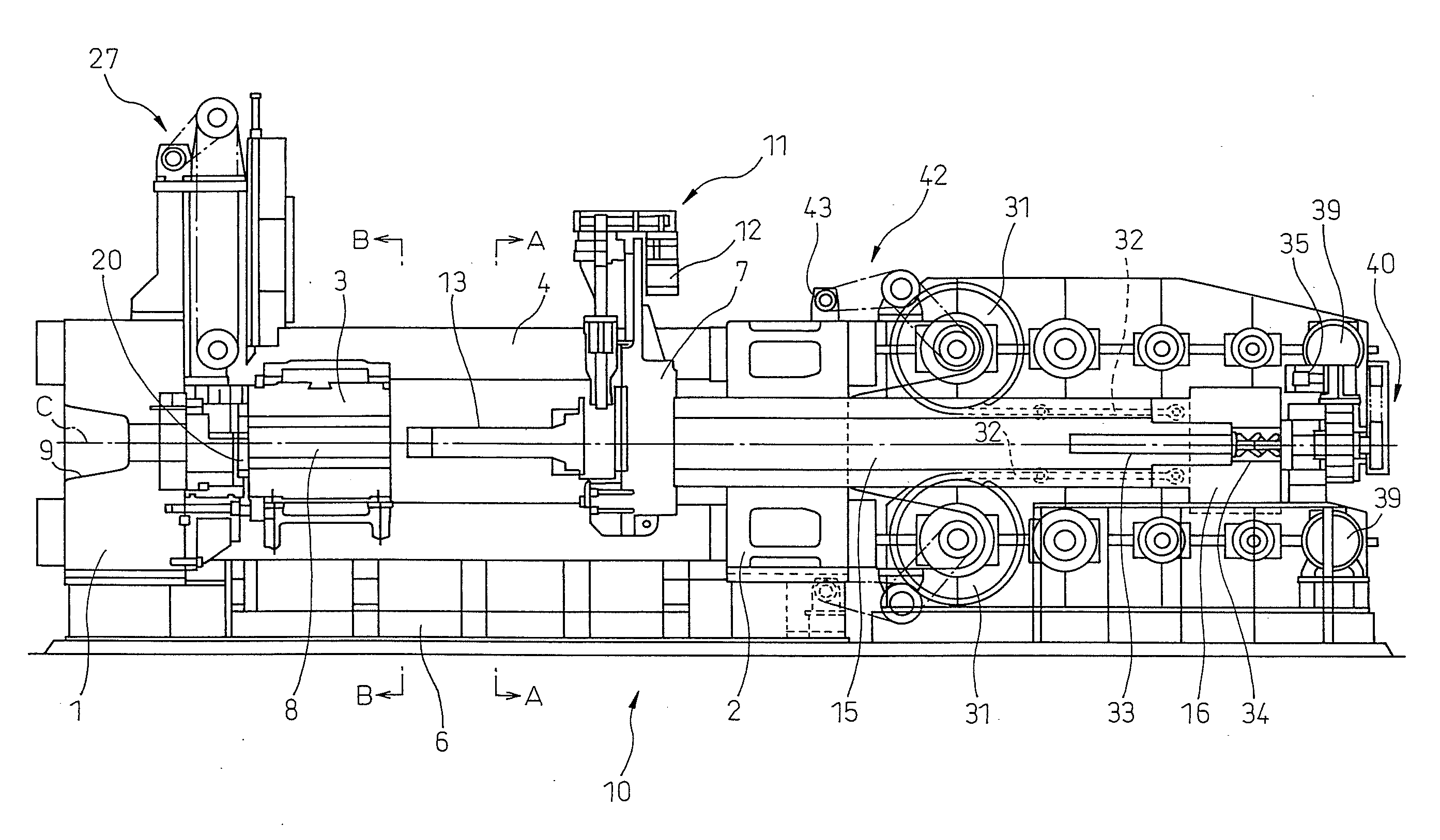
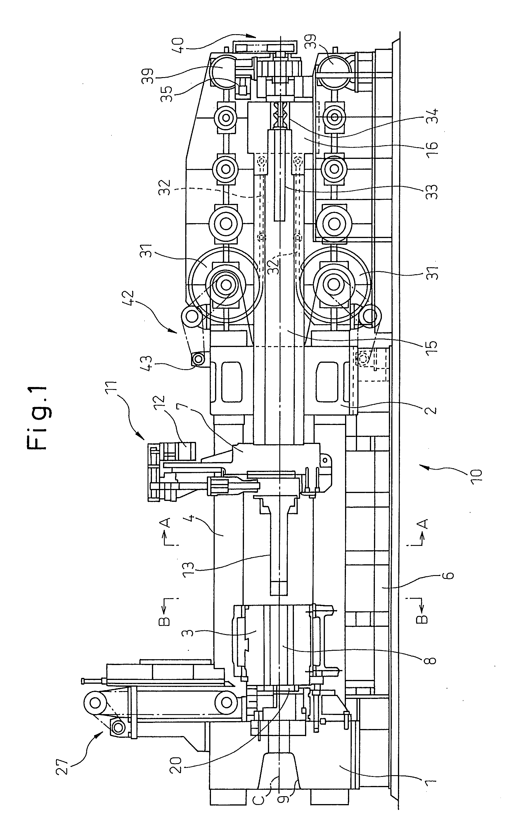
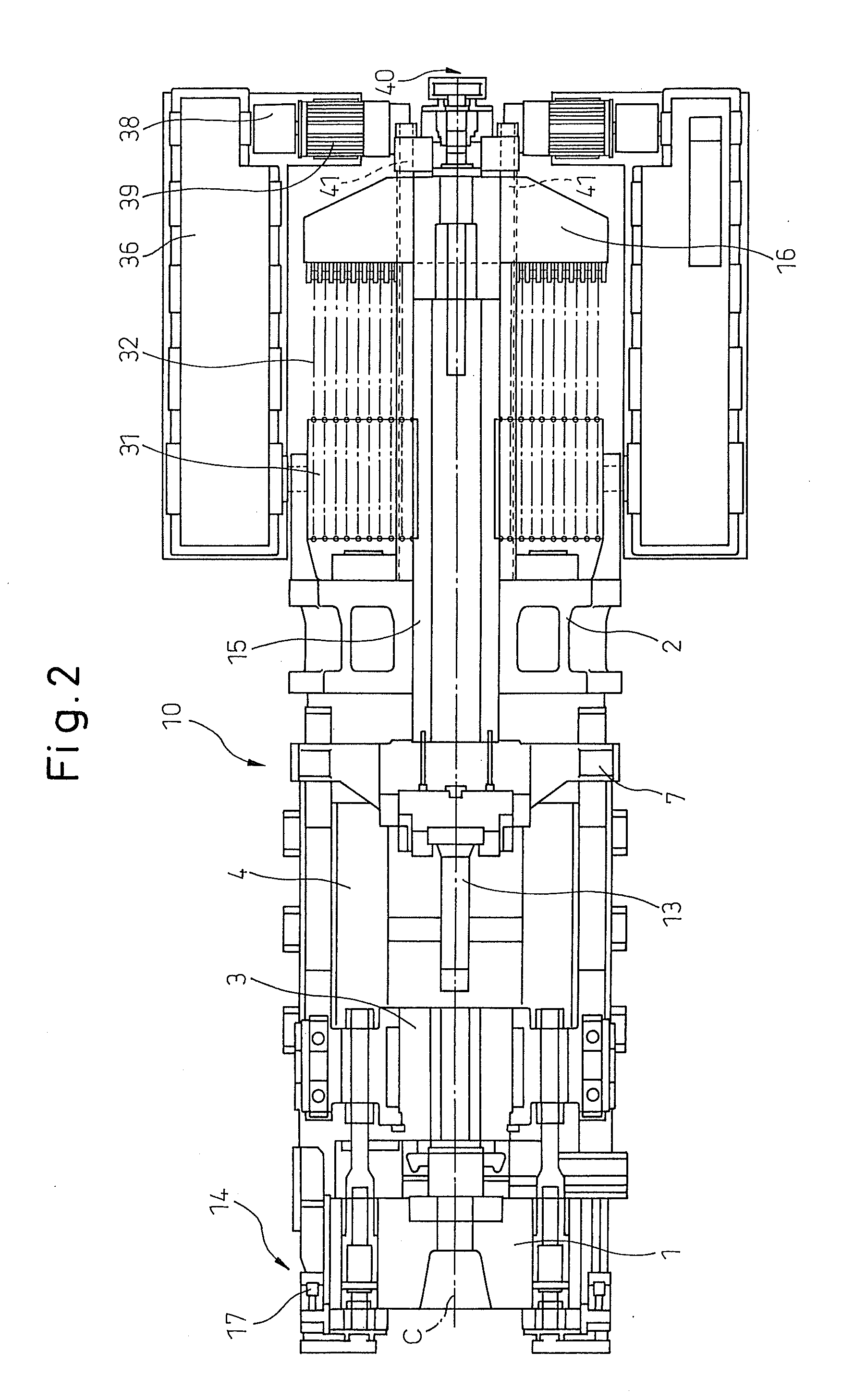
[0039]Referring to FIG. 1 and FIG. 2, an extrusion press 10 of the present invention comprises an end platen 1 located at the front end part and a fixed platen 2 located in the vicinity of the center of the device. At the center of the end platen 1, a through hole 9 is provided through which a product is caused to pass, which product is molded by extruding a billet 8 into a predetermined shape via a die 20. In the present embodiment, as can be seen clearly from FIG. 4, the end platen 1 and the fixed platen 2 are coupled by four tie rods 4 arranged in the four corners. Between the end platen 1 and the fixed platen 2, in the vicinity of the end platen 1, a container 3 to be loaded with the billet 8 is arranged so as to be supported by a container holder (not shown schematically) and on the side of the fixed platen 2, a crosshead 7 is arranged so as to be supported by the four tie rods 4. The tie rods 4 penetrate through the four corners of the crosshead 7, respectively. Between the en...

second embodiment

[0047]The container 3 is reciprocated (move forward and back) by the container operating motor 17, which is preferably an inverter motor or AC servomotor, via the mechanism including the ball screw and the ball and configured to convert rotational motion into linear motion. In the case of the front loading system (second embodiment to be described below), on the opposite side of the extrusion stem of the fixed platen, the container operating device 14, such as the container operating motor 17, is provided. This is because the movement stroke of the container is large. In the shear device 27, an electric motor is used as a power source and rotational motion is converted into rectilinear motion via the winding drive mechanism, such as a chain. The die slide device (shear) 21 uses an electric motor as a power source and converts rotational motion into rectilinear motion via the power transmission mechanism including the ball screw and the ball nut. The stem slider also uses an electric...


PUM

PropertyMeasurementUnit
pressureaaaaaaaaaa
speedaaaaaaaaaa
shapeaaaaaaaaaa

Abstract

To provide a fully electric extrusion press to reduce power consumption, improve maintenability and operability, and eliminate an adverse effect on the environment.An extrusion press (10) comprises an end platen (1), a fixed platen (2) arranged at the rear thereof, a tie rod (4) configured to link the end platen and the fixed platen, a die (20), a container (3) loaded with a billet (8), an extrusion stem (13) configured to press the billet, a crosshead (7) attached with the extrusion stem, and an extrusion drive configured to reciprocate the extrusion stem. The extrusion drive comprises a rotatable wire drum (31) driven by an electric extrusion main motor (39) and drives the extrusion stem to perform extrusion molding by winding the wire (30) by rotating the wire drum.

Description

BACKGROUND OF THE INVENTION[0001]1. Technical Field[0002]The present invention relates to an extrusion press and in particular, to an extrusion press device that molds an aluminum alloy, etc., by extrusion molding via a die and, in more particular, to an electrically driven extrusion press that applies the electrically driven system adopted in an injection molding machine of synthetic resin (or a die cast machine that die-casts an aluminum alloy).[0003]2. Background Art[0004]An extrusion press is used to mold a metal product, such as an aluminum sash, by extrusion molding. In the conventional extrusion press, a billet, which is a material, is loaded within a fixed container, extruded by a stem (or extrusion stem) driven by a ram cylinder, and passed through a die attached to the outlet of the container, and thereby, the billet is molded so as to have a predetermined cross-sectional shape. The billet loaded on such a molding machine is supplied by a billet loader. The billet loader i...

Claims


Application Information

Patent Timeline
Patent Type & Authority Applications(United States)
IPC IPC(8): B29C47/10
CPCB21C23/211
Inventor YAMAMOTO, TAKEHARU
Owner UBE MASCH CORP LTD
Why Eureka
Try Eureka