Reciprocating reactor and methods for thermal decomposition of carbonaceous feedstock
Inactive Publication Date: 2012-11-15
INTERRA ENERGY
View PDF19 Cites 32 Cited by
Summary
Abstract
Description
Claims
Application Information
AI Technical Summary
This helps you quickly interpret patents by identifying the three key elements:
Problems solved by technology
Method used
Benefits of technology
[0019]The present technology relates to systems, methods, and apparatus for the continuous thermal conversion of carbonaceous feedstock int
Problems solved by technology
This is problematic for two main reasons.
First, any level of combustion decreases pyrolysis product yields.
Second, the inert gases in the injected air and the combustion products dilute the pyrolysis gas products, making them less useful and often unburnable, which results in increased air pollution.
Notably, the heat source required to heat the vessel adds to the operational cost of such systems.
Also, using combustion as the heat source creates an air emissions source that can be detrimental to the environment.
Upgrading the gas can be expensive and is highly dependent on the chosen method.
The least expensive method is usually dehumidification to extract out the majority of the water vapor that formed during reaction.
For these rea
Method used
Image
Click on the blue label to locate the original text in one second.
Reading with bidirectional positioning of images and text.
Examples
example 1
Start Up
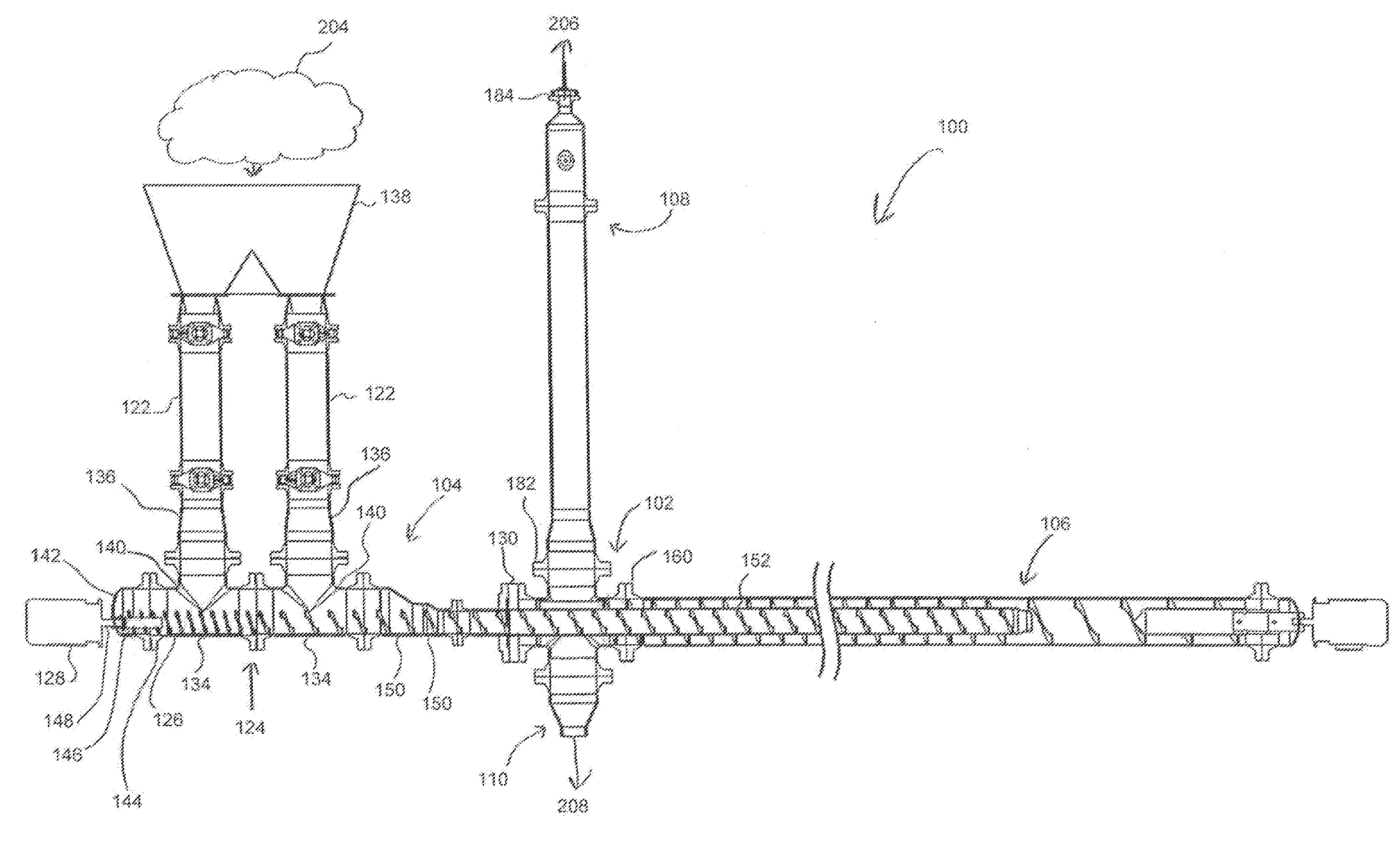
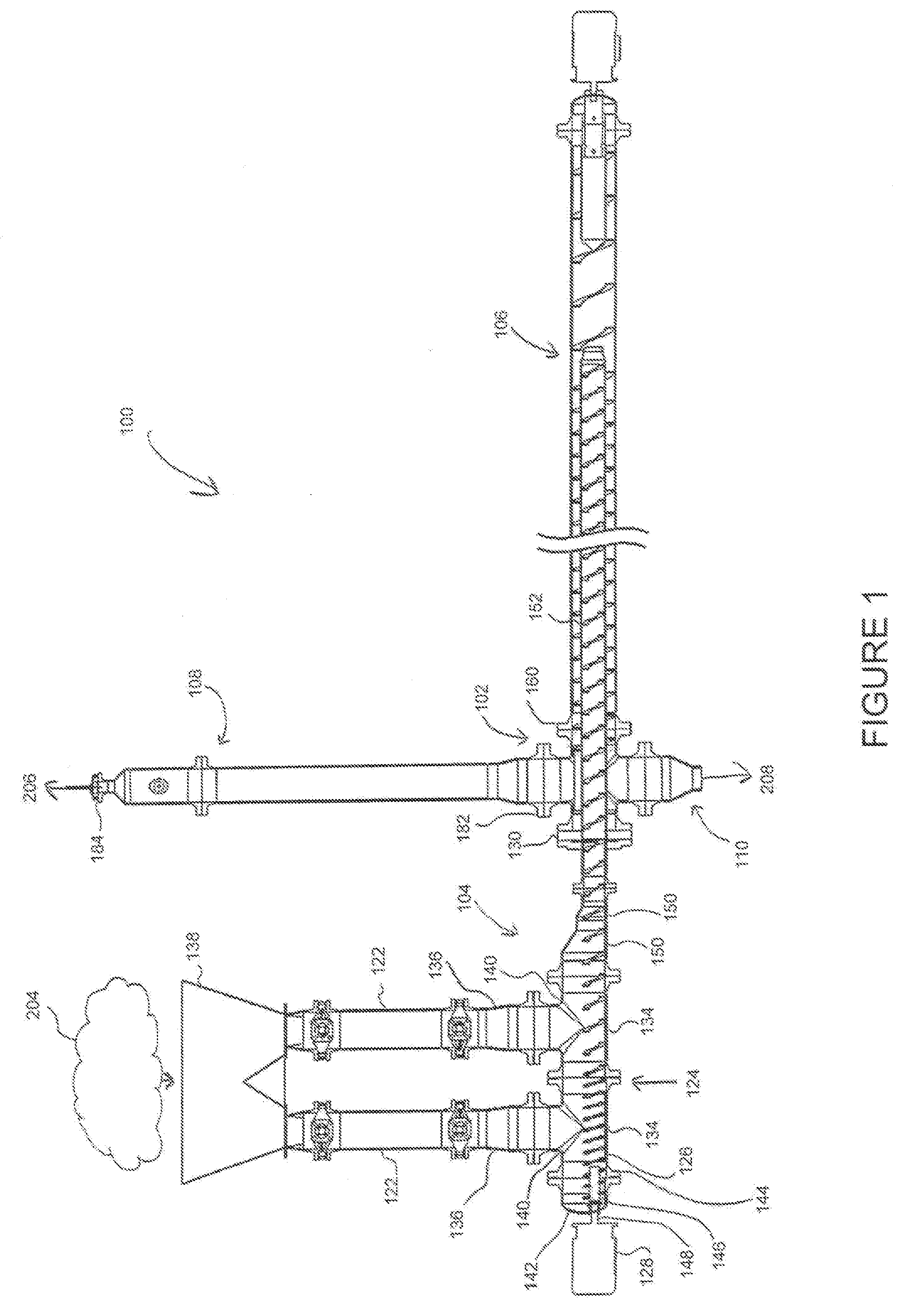
[0078]One example of a start-up procedure for a continuous pyrolysis system and process of the present technology is as follows:[0079]1. All airtight connections are closed except for the gas flow control valve 184 of the gas off-take system 108.[0080]2. Biochar is loaded into the continuous pyrolysis system 100 through the feed assembly 124, the amount of biochar being sufficient to fill the outer reactor zone 180.[0081]a. The last portion of biochar loaded is soaked with a small amount of slow-burning accelerant (e.g., diesel fuel). If biochar is left in the reactor from the last run, the slow-burning accelerant can be applied to the incoming biomass only.[0082]b. After stopping loading the biochar, the continuous pyrolysis system 100 continues to convey the biochar through the inner reactor zone 178 and into place in the outer reactor zone 180 with the slow-burning accelerant soaked portion of biochar positioned in the turnaround zone 164.[0083]3. After loading of the bio...
example 2
Shut Down
[0102]One example of a shutdown procedure for a continuous pyrolysis system and process of the present technology is as follows:[0103]1. Feeding of carbonaceous feedstock into the feeder assembly is ceased.[0104]2. The feed auger 126 and return auger 166 are operated until the gases and biochar exit the system.[0105]3. The feed auger126 and return auger 166 are shut off.
[0106]Alternatively, particularly where the expected time offline is short and the reactor does not need to be disassembled:[0107]1. Feeding of carbonaceous feedstock into the feeder assembly is ceased.[0108]2. The feed auger 126 and return auger 166 are operated until the all of the carbonaceous feedstock in the system reaches the outer reactor zone 180.[0109]3. The feed auger 126 and return auger 166 are shut off, and the biochar is allowed to cool to be ready for the next start up.
PUM
Abstract
The present technology discloses apparatus, systems, and methods for the thermal decomposition of carbonaceous feedstocks through continuous pyrolysis. A reciprocating reactor is disclosed that includes an inner reactor pipe and an outer reactor pipe. The outer reactor pipe has a first portion that surrounds the inner reactor pipe forming an annulus space, and a second portion that extends beyond the inner reactor pipe and forms a turnaround zone. The inner reactor pipe defines an inner reactor zone that produces partially reacted carbonaceous feedstock, and the annulus space defines an outer reactor zone that produces product gases and solids.
Description
RELATED APPLICATIONS[0001]This application claims priority to U.S. Provisional Application Ser. No. 61 / 486,231, filed on May 14, 2011, currently pending, the disclosure of which is hereby incorporated by reference in its entirety.FIELD OF THE INVENTION[0002]The present technology relates to methods, systems, and apparatus for the thermal decomposition of carbonaceous feedstocks.DESCRIPTION OF RELATED ART[0003]Pyrolysis is a process for the thermal conversion, or decomposition, of carbonaceous feedstocks, sometimes referred to as biomass, to produce biochar, water, and gases.[0004]The term “carbonaceous feedstock” includes all sorts of organic material, such as woody and herbaceous plant material and agricultural residues, including for example wood logs, slabs, chips, and bark, corncobs, corn stover, wheat straw, nutshells, and sugar cane bagasse. Carbonaceous feedstocks may also include the organic fraction of municipal solid wastes, plastics, tire, sewage sludge, manure, or other ...
Claims
Application Information
Patent Timeline
Application Date:The date an application was filed.
Publication Date:The date a patent or application was officially published.
First Publication Date:The earliest publication date of a patent with the same application number.
Issue Date:Publication date of the patent grant document.
PCT Entry Date:The Entry date of PCT National Phase.
Estimated Expiry Date:The statutory expiry date of a patent right according to the Patent Law, and it is the longest term of protection that the patent right can achieve without the termination of the patent right due to other reasons(Term extension factor has been taken into account ).
Invalid Date:Actual expiry date is based on effective date or publication date of legal transaction data of invalid patent.