Orthogonal ion injection apparatus and process

a technology of orthogonal ion injection and ion injection, which is applied in the direction of electrostatic deflection of tubes, separation processes, particle separator tube details, etc., can solve the problems of inability to fully solve liquid droplets generated, contamination of downstream components of mass spectometers, and unstable signals, so as to reduce noise and contamination, improve system sensitivity, and minimize contamination of downstream components

Active Publication Date: 2012-11-29
BATTELLE MEMORIAL INST
View PDF4 Cites 48 Cited by
  • Summary
  • Abstract
  • Description
  • Claims
  • Application Information

AI Technical Summary

Benefits of technology

[0023]The present invention accommodates greater gas loads in concert with a larger (e.g., 1 mm) acceptance inlet capillary thereby improving the sensitivity of the system while reducing noise and contamination.
[0024]In various embodiments, excess gas and liquid droplets is removed from the ion guide to minimize contamination of downstream components. The process improves transmission efficiency while simultaneously minimizing potent

Problems solved by technology

However, when an inline capillary is used to introduce ions into the ion funnel, any incompletely desolvated liquid droplets generated by the ESI are inadvertently entered into the ion funnel and subsequently carried into the mass spectrometer due to the pressure gradient.
In line approaches can thus cause contamination of downstream components of mass spectrometers.
This problem is more pronounced with multiple inlet capillaries used to increase the analyte signal, as multiple inlet capillaries significantly increase the quantity of ions introduced into the mass spectrometer, e.g., by as much as five-fold compared to single inlet capillaries with the same internal diameter (I.D.).
The introduction of large volumes of gas can lead to rapid contamination of downstream mass spectrometer elements, thereby resultin

Method used


Image

  • Orthogonal ion injection apparatus and process
  • Orthogonal ion injection apparatus and process
  • Orthogonal ion injection apparatus and process

Examples


Embodiment Construction

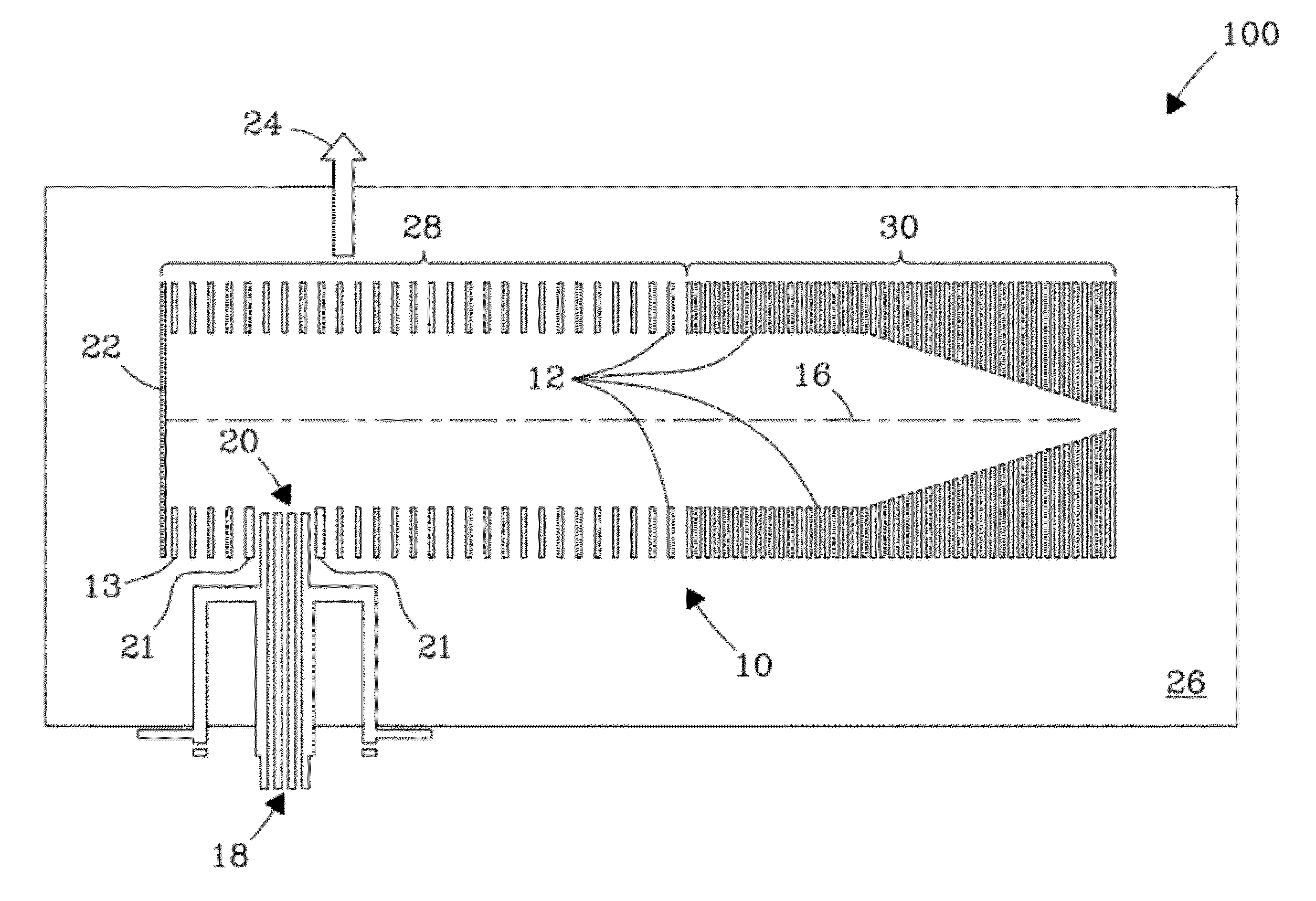
[0036]The present invention includes an orthogonal ion injection device and process for introducing ions into an ion guide that minimizes contamination of downstream mass spectrometer elements that normally would result in unstable signals and loss of signal over time. The present invention solves contamination problems known in the art by preventing liquid droplets generated by the ionization source (e.g., ESI sources) from entering into the mass spectrometer. While the present invention is described in reference to specific embodiments configured with a specific type of ion guide (e.g., an electrodynamic ion funnel), the invention is not limited thereto. For example, the invention can deliver ions in concert with various ion guides including, but not limited to, e.g., electrodynamic ion funnels, ion funnel traps, tandem ion funnels, S-lenses, stacked ring ion guides, including combinations of these various ion guides and associated components. Thus, all modifications as will be ma...


PUM


Abstract

An orthogonal ion injection apparatus and process are described in which ions are directly injected into an ion guide orthogonal to the ion guide axis through an inlet opening located on a side of the ion guide. The end of the heated capillary is placed inside the ion guide such that the ions are directly injected into DC and RF fields inside the ion guide, which efficiently confines ions inside the ion guide. Liquid droplets created by the ionization source that are carried through the capillary into the ion guide are removed from the ion guide by a strong directional gas flow through an inlet opening on the opposite side of the ion guide. Strong DC and RF fields divert ions into the ion guide. In-guide orthogonal injection yields a noise level that is a factor of 1.5 to 2 lower than conventional inline injection known in the art. Signal intensities for low m/z ions are greater compared to convention inline injection under the same processing conditions.

Description

[0001]This invention was made with Government support under Contract DE-AC05-76RLO1830 awarded by the U.S. Department of Energy. The Government has certain rights in the invention.FIELD OF THE INVENTION[0002]The present invention relates generally to instrumentation and methods for guiding and focusing ions in the gas phase. More particularly, the invention relates to a process for injection of ions into on guides for sensitive and robust mass spectral analysis that provides enhanced instrument stability.BACKGROUND OF THE INVENTION[0003]Electrospray ionization (ESI) sources that are coupled to on funnels often use an inline capillary (e.g., single or multiple) to introduce ions into the mass spectrometer (MS). FIG. 1 shows a conventional inline approach, in which a heated capillary is used to introduce ions from the ESI source directly into the ion funnel. The ion funnel then efficiently introduces ions into the mass spectrometer. However, when an inline capillary is used to introdu...

Claims


Application Information

Patent Timeline
IPC IPC(8): H01J49/22H01J49/00
CPCH01J49/065H01J49/044H01J49/0404
Inventor KURULUGAMA, RUWAN T.BELOV, MIKHAIL E.
Owner BATTELLE MEMORIAL INST
Why Eureka
Try Eureka