Drilling rig system with self-elevating drill floor

a drilling rig and floor technology, applied in the direction of ceilings, cranes, building repairs, etc., can solve the problems of increasing the set-up, take-down and operational costs of the rig, the wellbore is not sufficiently productive to warrant completion and operation of the well, and the equipment and labor costs can be incurred for each end of the set-up and take-down operation. to achieve the effect of facilitating the lateral movement of the completed rig base structure and facilitating the leveling

Inactive Publication Date: 2012-12-06
NAT OILWELL VARCO LP
View PDF19 Cites 53 Cited by
  • Summary
  • Abstract
  • Description
  • Claims
  • Application Information

AI Technical Summary

Benefits of technology

[0014]The rig apparatus includes a rig base structure comprising a plurality of base towers that can be positioned in a suitable spaced relationship on a wellsite. In one embodiment, there are four base towers arranged in a square or rectangular pattern, but other embodiments could use more than four towers and as few as three, and possibly in different (i.e., non-rectilinear) patterns. A generally horizontal base frame is installed between lower regions of the towers, thus tying the towers together to form a suitably rigid and stable rig base structure. The towers may be provided with height adjustment mechanisms (e.g., hydraulic jacks) to facilitate leveling the base structure over uneven ground surfaces. As well, the towers may optionally be provided with “walking” mechanisms whereby the lateral positions of the towers can be adjusted prior to installation of the horizontal base frame. The walking mechanisms can be coupled for cooperative actuation to facilitate lateral movement of the completed rig base structure.
[0015]A drill floor can then be constructed over the horizontal base frame of the rig base structure. The drill floor may comprise multiple slab sections that are anchored to each other after being positioned over the base frame to form an integral drill floor structure. Optionally, the horizontal base frame can be advantageously set at a height above ground corresponding to the level of a flatbed truck or trailer, thus facilitating unloading of drill floor sections by shifting them laterally off the trailer bed onto the base frame. The drill floor is mated to the towers with suitable guide means such that the drill floor can be uniformly elevated relative to the towers, with the towers acting to provide lateral stability to the drill floor at all stages of the floor-elevating process. When the drill floor has been elevated to the required elevation, it is locked to the towers by any suitable means, such as but not limited to hydraulic clamps.

Problems solved by technology

Conventional types of transportable rigs may require auxiliary support equipment to facilitate the erection and disassembly of large components such as the base, the drill floor, and the pipe racking board, thereby increasing rig set-up, take-down, and operational costs.
Further complicating the rig-up process is the common need to relocate the rig to a more promising site after a wellbore has been drilled and it has been determined that the wellbore will not be sufficiently productive to warrant completion and operation of the well.
Typically, rig take-down and set-up times are in the order of days, and very large equipment and labor costs can be incurred for each end of a set-up and take-down operation.
Various prior art drilling rigs are geared towards facilitating rapid set-up, take-down and transport, but they still require auxiliary equipment such as external cranes and external winches, which most often need to be leased and therefor increase overall rig set-up and take-down costs, particularly for remote wellsites.
However, this system has an inherent drawback in that the rig floor raising procedure has to be carried out in incremental and comparatively complex stages, and is correspondingly complex and time-consuming.
In addition, the Wasterval system entails the provision of a robust hydraulic system, which might not otherwise be needed on site during rig-up, and thus increases rig-up costs.
As well, the Wasterval system requires the use of mobile cranes or other auxiliary hoisting equipment to manipulate and position the box beams, further adding to rig-up costs.

Method used


Image

  • Drilling rig system with self-elevating drill floor
  • Drilling rig system with self-elevating drill floor
  • Drilling rig system with self-elevating drill floor

Examples


Embodiment Construction

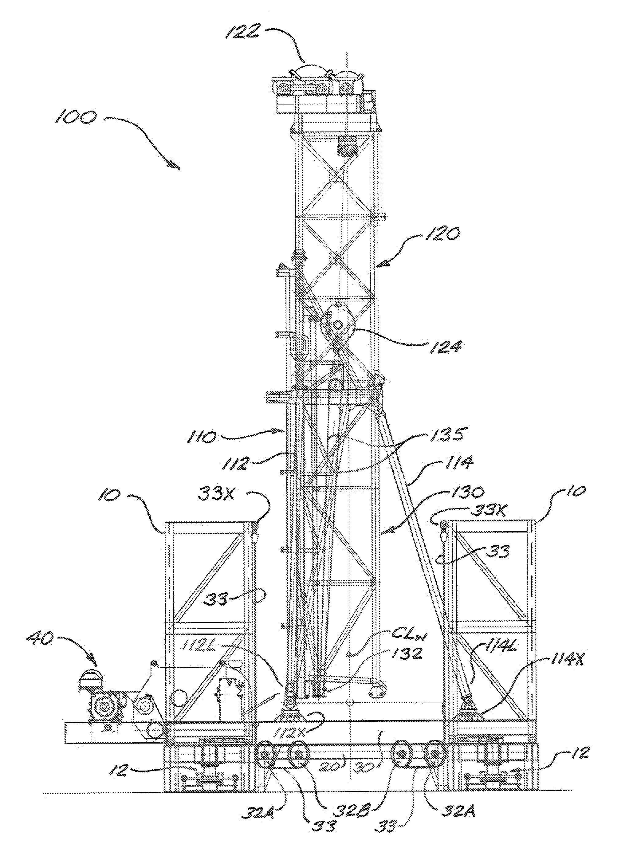
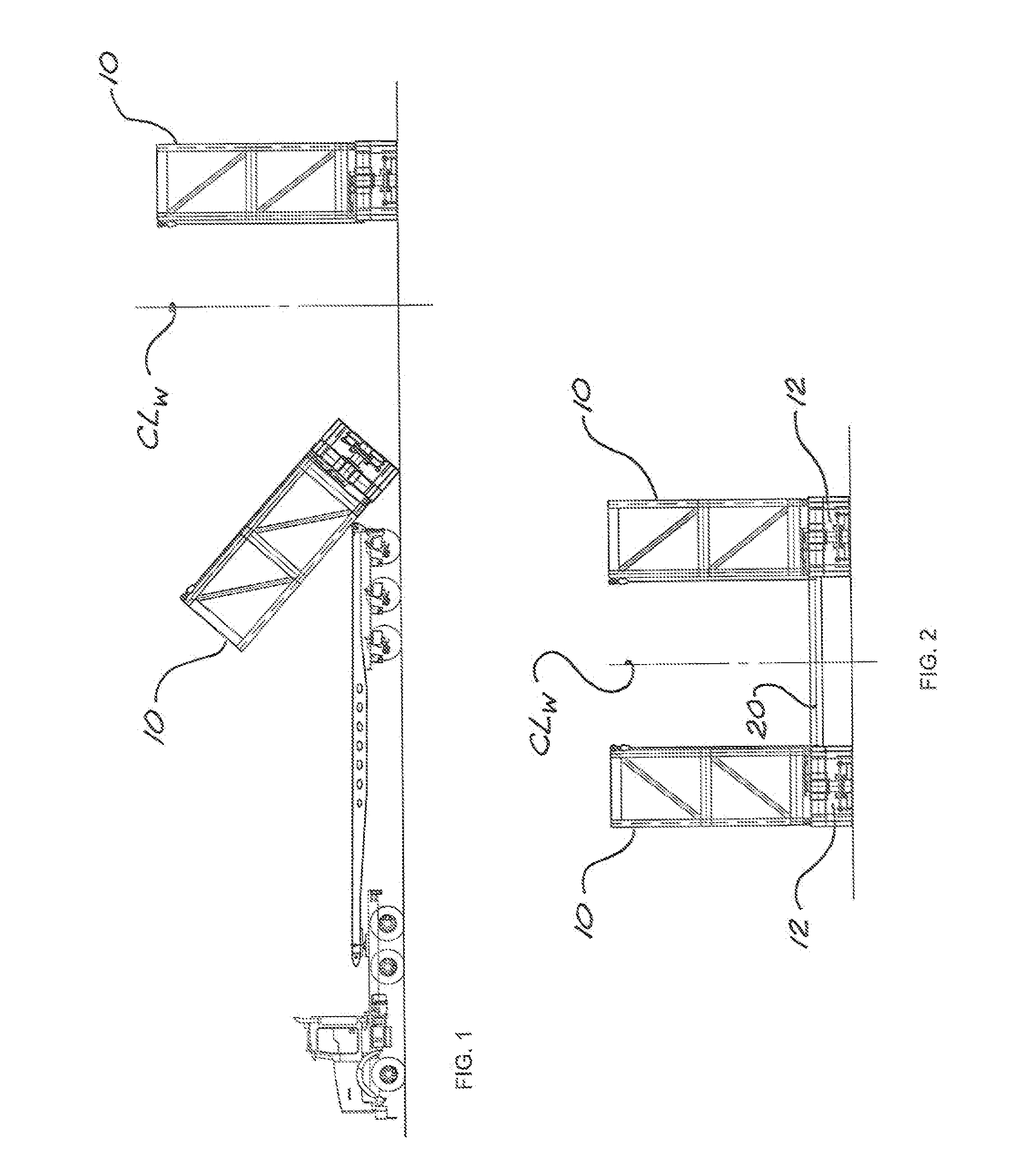
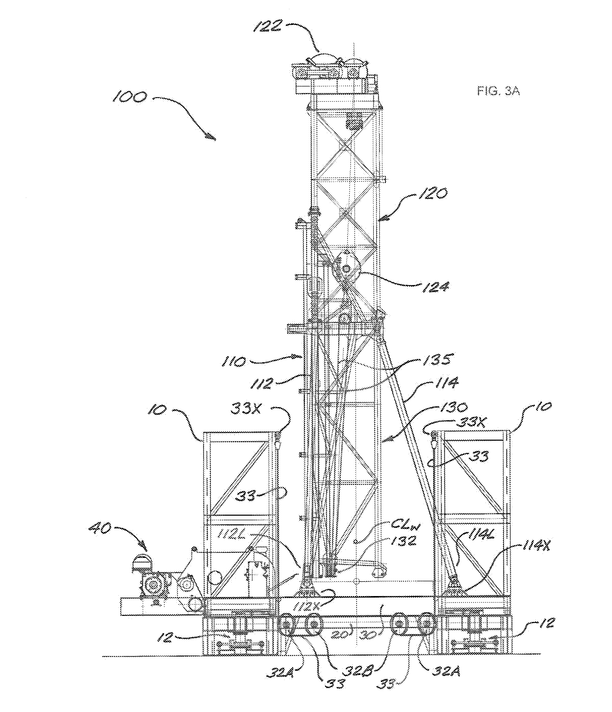
[0027]FIGS. 1 through 5B progressively illustrate the steps involved in assembling one embodiment of a transportable drilling rig in accordance with present disclosure. FIGS. 1 and 2 depict the delivery and positioning of a plurality of base towers 10 at a drill site. Preferably (but not necessarily), towers 10 will be provided with adjustment means 12 for adjusting their height, lateral position, and vertical alignment. Persons skilled in the art will know that such means can be provided in a variety of ways using known technologies, and such means do not constitute components of the broadest embodiments of drilling rigs in accordance with this disclosure.

[0028]After the required number of towers 10 are in their required positions relative to the centerline CLW of a wellbore to be drilled using the rig being constructed, a base frame 20 is constructed or installed as shown in FIG. 2, interconnecting the base towers 10. Base frame 20 can be of any suitable layout and structural conf...


PUM


Abstract

A transportable drilling rig having a self-elevating drill floor includes a base structure comprising multiple base towers that can be transported to a wellsite and positioned around an intended wellbore location. A horizontal base frame is installed between lower regions of the towers to form a stable rig base structure, and a drill floor can then be constructed over the base frame and between the base towers. A suitable rig mast can then be erected on the drill floor. Floor-lifting cables are anchored to upper regions of the base towers and disposable around corresponding sheave assemblies associated with the drill floor. The free ends of the floor-lifting cables can be engaged by the traveling block in the rig mast, whereupon the rig's drawworks can be actuated to elevate the drill floor and mast as required and then locked to the base towers.

Description

CROSS-REFERENCE TO RELATED APPLICATIONS[0001]This application claims the benefit of U.S. Provisional Application No. 61 / 492,786, filed on Jun. 2, 2011, and said earlier application is incorporated herein by reference in its entirety for continuity of disclosure.FIELD OF THE DISCLOSURE[0002]The present disclosure relates in general to rig structures for drilling wells such as oil and gas wells. In particular, the disclosure relates to rig structures that can be readily transported, rapidly erected, and rapidly disassembled, and further relates to methods for erecting such rig structures.BACKGROUND[0003]Wells for the recovery of hydrocarbons or minerals from a subsurface formation are commonly drilled by connecting a drill bit onto the lower end of an assembly of drill pipe sections connected end-to-end (commonly referred to as a “drill string”), and then rotating the drill string so that the drill bit progresses downward into the earth to create the desired wellbore. The drill string...

Claims


Application Information

Patent Timeline
Patent Type & Authority Applications(United States)
IPC IPC(8): E04H12/34E04H12/00E04B1/343
CPCE21B15/00E04H12/344E04H12/345E04B1/34331E04B1/34384E04H12/18
Inventor KONDUC, KAMERON WAYNEBURLET, DONALD LEONARD
Owner NAT OILWELL VARCO LP
Why Eureka
Try Eureka