
Catalysts and electrodes for fuel cells

a fuel cell and catalyst technology, applied in the field of catalysts, can solve the problems of overpotential of hydrogen electrodes in regenerative fuel, membrane cannot completely prevent electrolyte crossover from one side of the cell, poisoning of hydrogen catalyst by halides, etc., and achieves the effect of high life and performance and low cos

Inactive Publication Date: 2012-12-06
RAMOT AT TEL AVIV UNIV LTD
View PDF4 Cites 15 Cited by
  • Summary
  • Abstract
  • Description
  • Claims
  • Application Information

AI Technical Summary

Benefits of technology

[0010]This disclosure generally relates to catalysts, and to electrodes comprising those catalysts, for use in fuel cells. More specifically, this disclosure relates to catalysts active towards HER and HOR and to porous electrodes which are made in a process designed to control their porosity, employed in regenerative fuel cells, comprising hydrogen and halogen acid or mixture of halogen acids. The catalysts are particularly useful in hydrogen / bromine reduction / oxidation reactions. The catalysts exhibit highly acceptable life and performance. The catalysts also have low cost that is attributable to low amounts of precious metals, e.g., platinum, present in the catalyst.

Problems solved by technology

An important issue connected to catalyst activity in regenerative fuel cells that utilize, for example, a halogen acid electrolyte, is poisoning of the hydrogen catalyst by the halides.
The membrane cannot completely prevent electrolyte crossover from one side of the cell to the other.
Despite the fact that hydrogen oxidation / evolution reaction is fast and its overpotential is rather low compared to other voltage losses in the regenerative cell, in halogen ion-containing solutions, the catalyst is severely poisoned, and this raises the overpotential of the hydrogen electrode in the regenerative fuel cell.
A problem common to porous electrodes is to provide the most effective pathway throughout the electrode for each reactant and product involved in the electrochemical reaction, and enhance a surface area between the active material and the electrolyte, making it as large as possible.
A major drawback of porous electrodes is flooding of the electrodes.
For regenerative fuel cell such as hydrogen / bromine fuel cells, an important factor limiting its cycle life is the degradation of the operating fuel cell materials.
These materials are exposed to a highly corrosive bromine electrolyte for long periods of time at elevated temperature.
In reality, the membranes do, not completely prevent bromide ions from passing through the membrane and adsorbing on the hydrogen electrode.
As a result of this, the hydrogen / bromine fuel cell cycle life becomes limited because of several reasons including catalyst corrosion and poisoning of the hydrogen catalyst.

Method used


Image

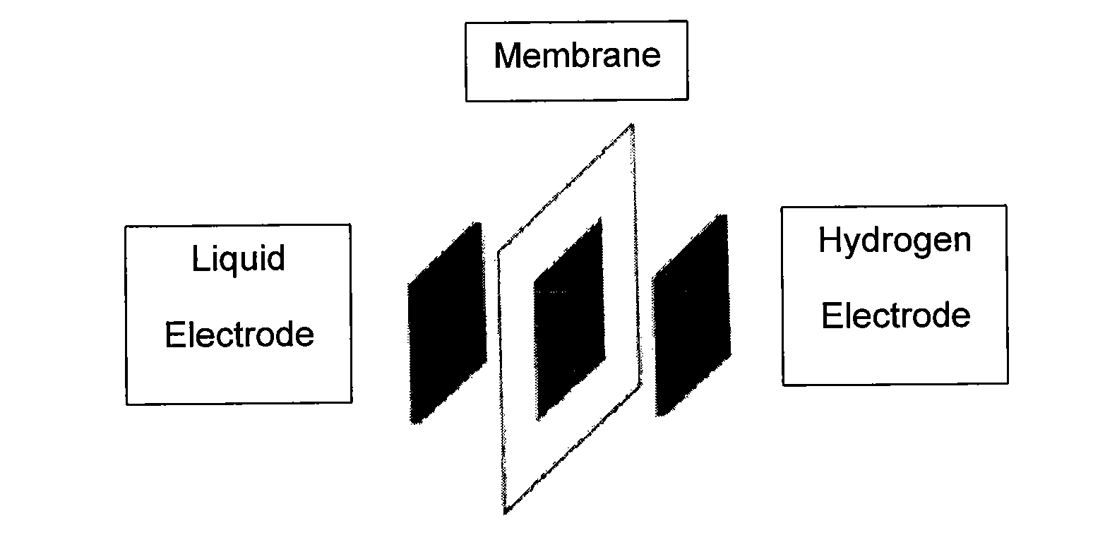
  • Catalysts and electrodes for fuel cells
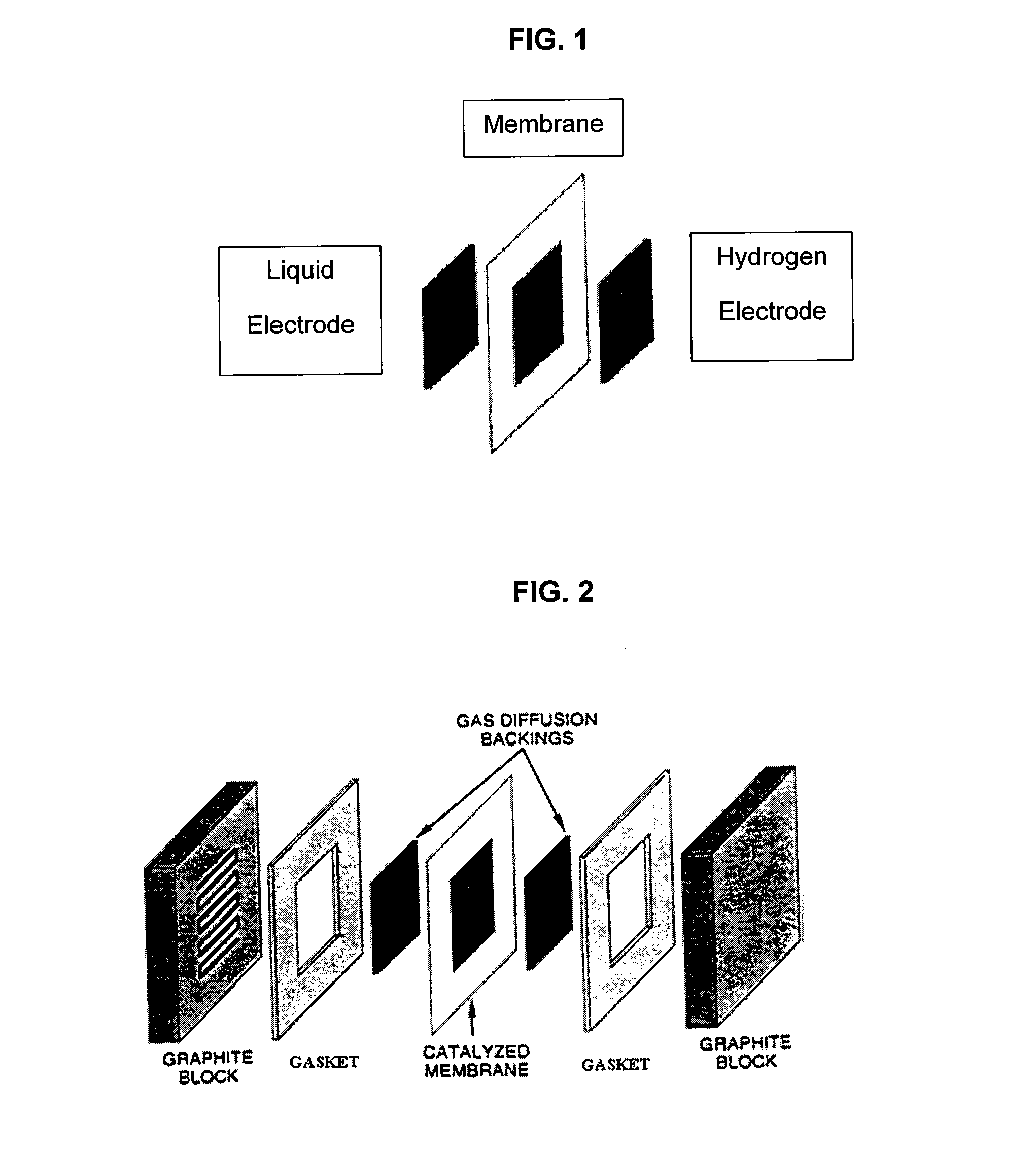
  • Catalysts and electrodes for fuel cells
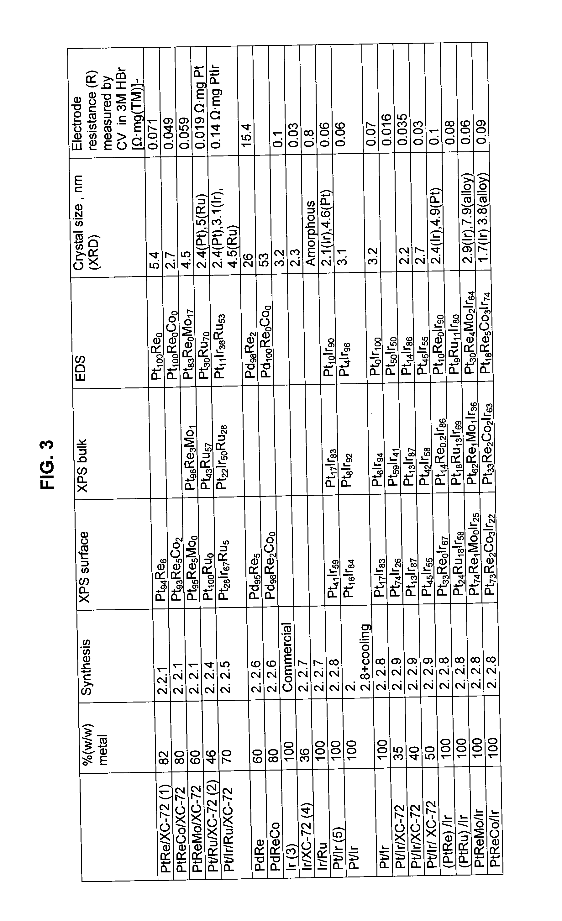
  • Catalysts and electrodes for fuel cells

Examples


example 1

60% (w / w) Pt94Re6 / XC-72 Synthesis

[0111]0.200 g of XC-72 was added to 100 ml 0.4M HCl. 0.519 g of PtCl4 and 0.840 g of NaReO4 were added to the obtained slurry while stirring. The slurry was kept under stirring for 1 hour. 10 ml of NH4OH were added to the slurry in small portions. The pH of the solution was 11-12. 0.524 g NaBH4 were dissolved in 10 ml H2O and added to the slurry rapidly and in one portion. The slurry was kept under stirring for 1 h. The catalytic powder obtained was recovered by centrifugation, treated in 1M H2SO4 at 80° C. for 8 hours, washed with distilled water until no chloride ions could be detected and dried by evaporation.

[0112]In case of PtReCo and PtReMo the precursors that were added to the solution in synthesis 2.2.1 in FIG. 3 for Co and Mo were CoCl2.6H2O and (NH4)6Mo7O24.4H2O respectively.

example 2

30% (w / w) PtCr / XC-72

[0113]1.4 g XC-72 were suspended in 100 ml of H2O and XC-72 was finely dispersed by sonicating for 15 min. The slurry was then stirred and 1.74 ml of about 69% HNO3 were added. 0.861 grams of PTA H2PtOH6 were added to 826 ml of 4.0M HNO3 in a separate flask. PTA solution was transferred to a carbon slurry and stirred for 30 min. The beaker was heated at 1° C. / min rate up to 70° C. and this temperature was maintained for 1 h under stirring. After the heating was stopped NH3 (about 30%) was added to the slurry at a rate of 10 ml / min, until reaching a pH between 3 and 3.5 and the solution was cooled down to room temperature under stirring. 0.378 grams of Cr(NO3)3.9H2O were dissolved in 50 ml water and added to a slurry and ultrasonicated. After 30 min the pH of the slurry was adjusted to about 4.5 with 0.5M NH4OH. After 30 minutes, the heating of the solution was resumed by raising temperature to 75° C. at 1° C. / min rate. The solution was stirred and pH was controll...

example 3

30% Ru / XC-72

[0114]Ru on carbon was synthesized by polyol process in ethylene glycol. A mix of 0.5 grams 1% (w / w) Pt / XC-72 and about 1 gram RuCl3 in 900 ml ethylene glycol was stirred for 0.3 hours at 170° C. The powder was filtered; washed in H2O and acetone and vacuum dried at 100° C. The powder was acid treated in 0.5 M H2SO4 at 80° C. for 8 hours, and washed in H2O.


PUM

PropertyMeasurementUnit
grain sizesaaaaaaaaaa
porosityaaaaaaaaaa
porosityaaaaaaaaaa

Abstract

A catalyst composition comprising at least one precious metal, wherein the catalyst composition is capable of catalyzing, in the presence of a halogen ion or a mixture of halogen ions, a charging reaction and a discharging reaction in a regenerative fuel cell. This disclosure relates to electrodes comprising those catalysts that are useful in fuel cells. The catalysts are active towards hydrogen evolution reaction (HER) and hydrogen oxidation reaction (HOR) and porous electrodes are made in a process designed to control their porosity. The catalysts and electrodes are employed in regenerative fuel cells comprising hydrogen and halogen acid or mixture of halogen acids. The catalysts are particularly useful in hydrogen / bromine reduction / oxidation reactions. The catalysts exhibit highly acceptable life and performance.

Description

BACKGROUND[0001]1. Field of the Disclosure[0002]This disclosure generally relates to catalysts, and to electrodes comprising those catalysts, for use in fuel cells. More specifically, this disclosure relates to catalysts active towards hydrogen evolution reaction (HER) and hydrogen oxidation reaction (HOR) and to porous electrodes which are made in a process designed to control their porosity, employed in regenerative fuel cells, comprising hydrogen and halogen acid or mixture of halogen acids. The catalysts are particularly useful in hydrogen / bromine reduction / oxidation reactions. The catalysts exhibit highly acceptable life and performance.[0003]2. Discussion of the Background Art[0004]A typical fuel cell consists of two electrodes, an anode and a cathode, and a membrane interposed between the anode and cathode. Fuel cells operate by converting fuel combustion energy, such as hydrogen, to electrical power through an electrochemical process. It does so by harnessing the electrons r...

Claims


Application Information

Patent Timeline
Patent Type & Authority Applications(United States)
IPC IPC(8): B01J23/656H01M4/92H01M4/96H01M8/10B01J23/652B01J23/89B01J23/46H01M4/90H01M8/18B82Y30/00C25B9/19
CPCH01M4/9083H01M4/921H01M4/926H01M4/96H01M8/0202Y02E60/50H01M8/0258H01M8/0271H01M8/186Y02E10/50Y02P70/50H01M4/90H01M8/02H01M8/04H01M8/24H01M8/1051
Inventor PELED, EMANUELBLUM, ARNONAHARON, ADITRAVITSKY, NINAKONRA, YARONSAADI, KOBBYZEL, VLADIMIRGOOR, MEITALALON, MEITALGORENSHTEIN, ROY
Owner RAMOT AT TEL AVIV UNIV LTD
Learn More