Data center battery enhancement method and system

Active Publication Date: 2012-12-13
LATHAM ANDREW V
View PDF29 Cites 21 Cited by
  • Summary
  • Abstract
  • Description
  • Claims
  • Application Information

AI Technical Summary

Benefits of technology

[0015]The above-described problems are addressed and a technical solution is achieved in the art by providing a system and method for increasing workable power output of a battery backup system. A plurality of battery groups each having a nominal voltage rating is provided. The powe

Problems solved by technology

Operating data centers is expensive with respect to floor space, cooling, energy demand needs, etc.
Battery systems and battery storage cabinets employed in data centers are also expensive, are heavy, and have maintenance needs proportional to their physical size, energy storage, and production.
It is not uncommon for a data center that experiences a complete power outage (i.e., a crash) and loses of all of its servers (without an orderly shutdown) to incur substantial monetary losses before re-starting.
When operated at four times rated consumption, these batteries are highly stressed in terms of a rapid rate of chemical reaction and production of heat.
The conventionally wired system 2 may be so large as to fill multiple rooms at considerable cost.
Unfortunately, each megawatt-hour of battery power may cost up to 125 thousand dollars or more and weigh as much as 30 thousand pounds, take up considerable space, and use significant power to recharge.
As a rule, the bigger the data center system and/or the bigger the battery back up system, the more cost and energy demand expense and footprint size.
Often these systems may be placed in a very expensive building that may be located in very expensive areas (e.g., Manhattan).
At this junction, chemicals may be consumed at such a high rate that they cannot be replenished rapidly enough.
As a result, energy output degrades and battery power (voltage)

Method used


Image

  • Data center battery enhancement method and system
  • Data center battery enhancement method and system
  • Data center battery enhancement method and system

Examples


Embodiment Construction

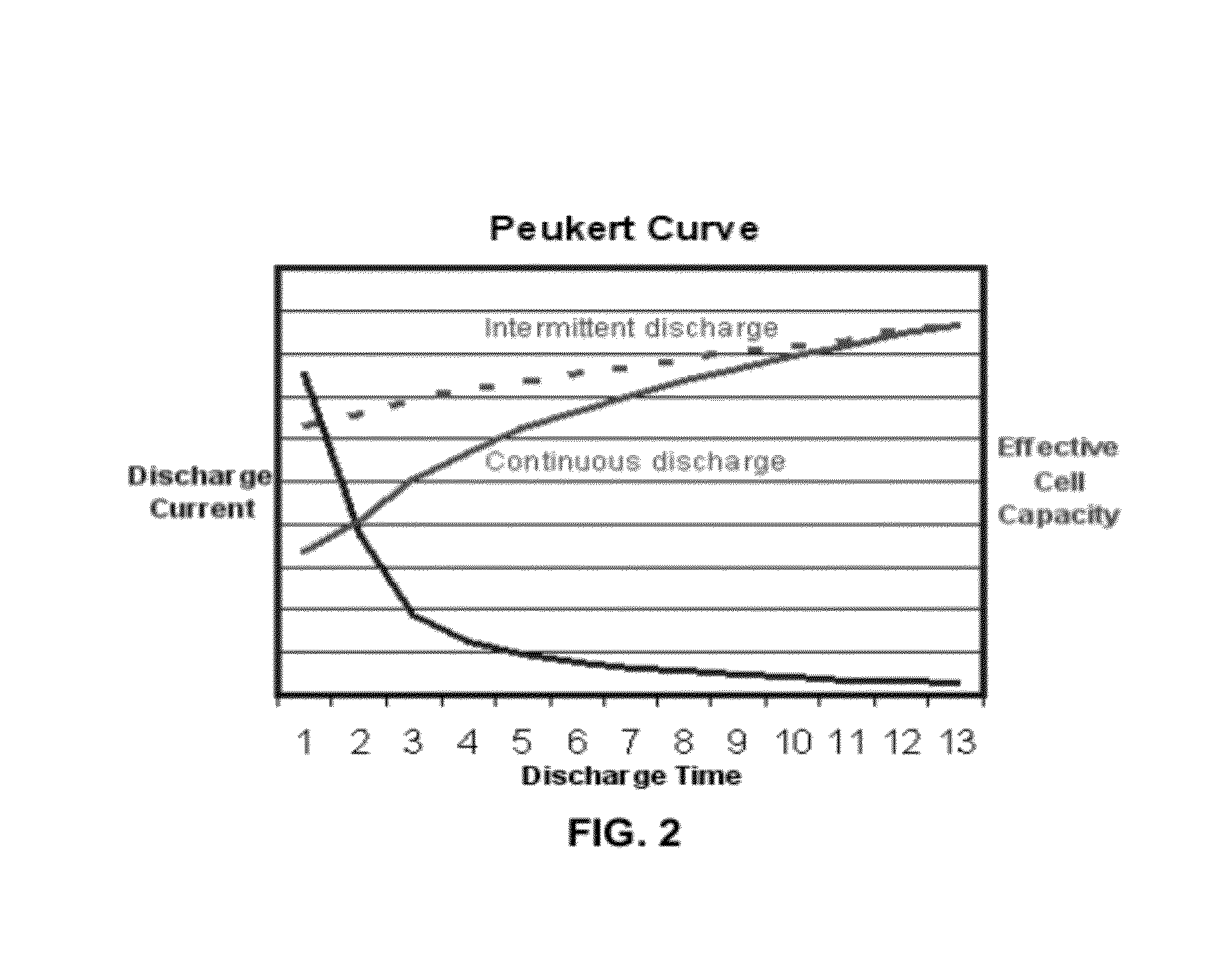
[0033]A consequence of Peukert's Law is that when a battery is discharged at its rated discharge rate, significantly more power may be made available over time. The battery may be discharged at a lowest rate possible, which is slightly above the battery's “self-discharge” rate.

[0034]FIG. 2 is a graph illustrating Peukert's curve in terms of effective cell capacity as measured by discharge current over discharge time. FIG. 2 illustrates that effective battery capacity is radically reduced at very high continuous discharge rates. However, with intermittent use, a battery may have time to recover during quiescent periods when its chemistry at the electrolyte cell interface has recovered due to diffusion and its temperature returns to an ambient level. Because of this potential for recovery, UPS run time capacity may be improved and operating efficiency may be increased (or fewer batteries may be needed or the same number of battery groups may be employed but with a smaller amp hour cap...


PUM


Abstract

A method for increasing workable power output and run time duration of a battery backup system is disclosed. A plurality of battery groups is provided. A microprocessor electrically connects the power output of a first battery group and a second battery group to a UPS. The microprocessor monitors the output voltage of the first and second battery groups. When the monitored output voltage of the first and second battery group falls below a predetermined level, the microprocessor electrically disconnects from the UPS the first battery group and electrically connects to the UPS the power output of another of the plurality of battery groups. The first battery group is configured to be re-connectable to the UPS after a time period equal to or greater than necessary to permit the output voltage of the first battery group to recover to about its nominal voltage rating.

Description

CROSS-REFERENCE TO RELATED APPLICATION[0001]This application claims the benefit of U.S. provisional patent application No. 61 / 494,573 filed Jun. 8, 2011, the disclosure of which is incorporated herein by reference in its entirety.FIELD OF THE INVENTION[0002]The invention relates generally to power systems. More specifically, the invention relates to a method and system for extending run time of existing battery backup systems or reducing the quantity of batteries needed for a set amount of run time of battery backup systems.BACKGROUND OF THE INVENTION[0003]Operating data centers is expensive with respect to floor space, cooling, energy demand needs, etc. Battery systems and battery storage cabinets employed in data centers are also expensive, are heavy, and have maintenance needs proportional to their physical size, energy storage, and production.[0004]Data centers employ battery-powered backup systems known as un-interruptable power supplies (UPS). These systems may be integrated i...

Claims


Application Information

Patent Timeline
IPC IPC(8): H02J9/00
CPCH02J1/102H02J7/0018H02J2007/0067H02J7/085H02J9/061H02J7/0063H02J7/007182H02J7/0025H02J9/06
Inventor LATHAM, ANDREW V.
Owner LATHAM ANDREW V
Why Eureka
Try Eureka