
Self-Driven Synchronous Rectification Boost Converter Having High Step-Up Ratio

Active Publication Date: 2012-12-13
TCL CHINA STAR OPTOELECTRONICS TECH CO LTD
View PDF4 Cites 2 Cited by
  • Summary
  • Abstract
  • Description
  • Claims
  • Application Information

AI Technical Summary

Benefits of technology

[0006]The present invention provides a self-driven synchronous rectification boost converter having high step-up ratio to overcome the problem of high power-consumption on using diode rectifier in the conventional technology.
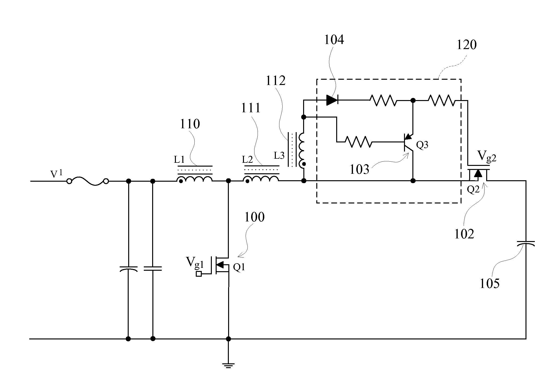
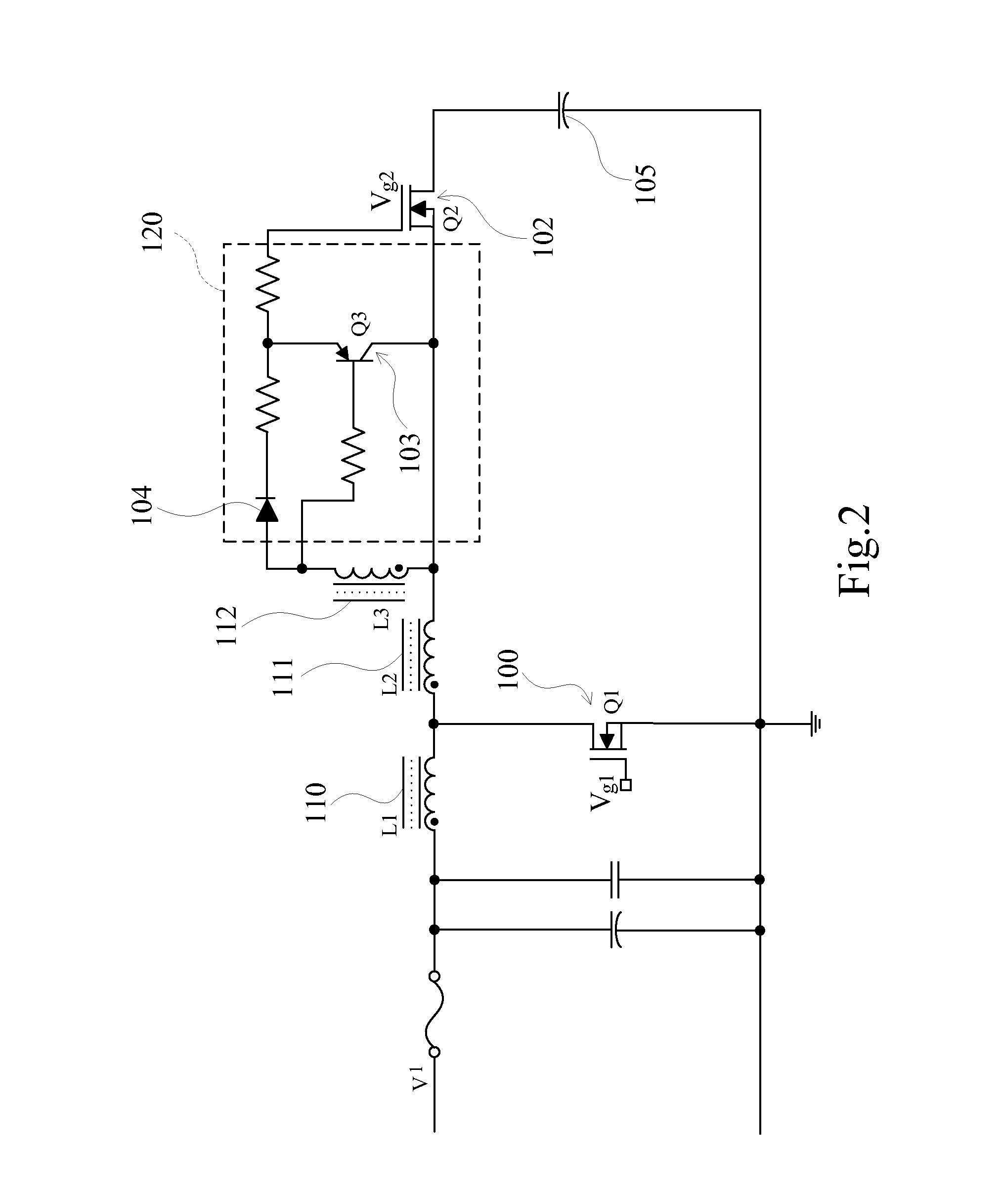
[0020]The present invention is to use the coupling of the auxiliary winding and the second winding to control the action of rectifying switch with a switch circuit. The present invention implements a self-driven synchronous rectification that replaces conventional diode rectification technology, enhances operation efficiency and lowers power-consumption.

Problems solved by technology

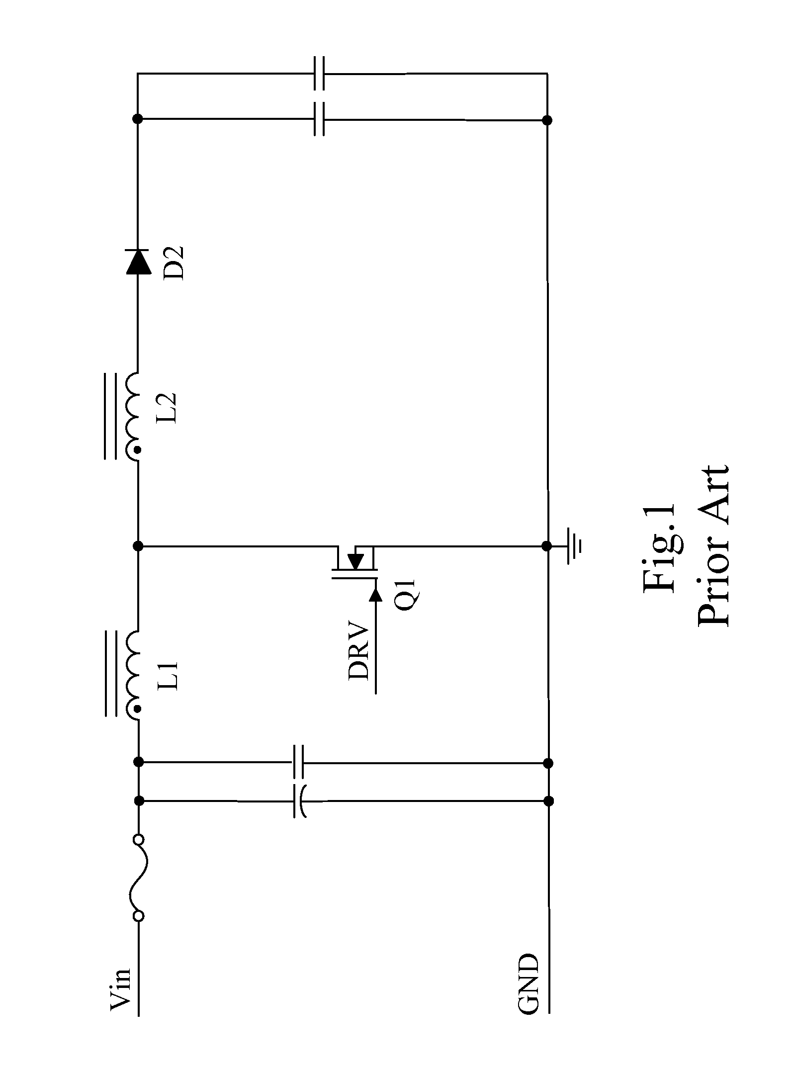
However, since the boost circuit uses the diode D2 for rectification, as the circuit outputs a large current, power consumption of the diode will become higher and cause the efficiency of the boost circuit to decrease and a problem of heat dissipation.
If the boost circuit uses a MOSFET for rectification, the circuit needs to be driven with a floating ground isolation, which causes design of the circuit to be more complicated.

Method used


Image

  • Self-Driven Synchronous Rectification Boost Converter Having High Step-Up Ratio
  • Self-Driven Synchronous Rectification Boost Converter Having High Step-Up Ratio
  • Self-Driven Synchronous Rectification Boost Converter Having High Step-Up Ratio

Examples


Embodiment Construction

[0024]The foregoing objects, features and advantages adopted by the present invention can be best understood by referring to the following detailed description of the preferred embodiments and the accompanying drawings. Furthermore, the directional terms described in the present invention, such as upper, lower, front, rear, left, right, inner, outer, side and etc., are only directions referring to the accompanying drawings, so that the used directional terms are used to describe and understand the present invention, but the present invention is not limited thereto.

[0025]With reference to FIG. 2, FIG. 2 is a circuit diagram of a preferred embodiment of a self-driven synchronous rectification boost converter having high step-up ratio in accordance with the present invention. The self-driven synchronous rectification boost converter having high step-up ratio mainly comprises a first switch 100, a first winding 110, a second winding 111, an auxiliary winding 112, a switch circuit 120 an...


PUM


Abstract

The present invention provides a self-driven synchronous rectification boost converter having high step-up ratio. The self-driven synchronous rectification boost converter having high step-up ratio has a first switch receiving a pulse driving signal, a first winding, a second winding and a synchronous rectification circuit constructed by an auxiliary winding and a second switch. The first winding inducts a reverse voltage when the first switch is repeatedly switched on and off. The reverse voltage then is raised via the second winding, and the auxiliary winding cooperates with a switch circuit to switch on / off the second switch according to an inducted voltage, so as to achieve an object of synchronous rectification. Under a condition of outputting high current, the present invention can greatly reduce power-consumption of rectifying and enhance efficiency.

Description

FIELD OF THE INVENTION[0001]The present invention relates to a boost converter, and more particularly to a self-driven synchronous rectification boost converter having high step-up ratio.BACKGROUND OF THE INVENTION[0002]With reference to FIG. 1, a conventional boost circuit for driving a backlight module of a liquid crystal display device mainly has an input power Vin, a first winding L1 connected to the input power Vin, a second winding L2 connected to the first winding L1, a diode D2 connected between the second winding L2 and an output capacitor, and a transistor switch Q1.[0003]The boost circuit uses the action of repeatedly switching on-and-off of the transistor switch Q1 to control the first winding L1 to output an forward-biased voltage, and then to raise the voltage with the number of windings of the second winding L2 being larger than the number of windings of the first winding L1, so that the output capacitor can provide an output voltage higher than the input voltage Vin ...

Claims


Application Information

Patent Timeline
IPC IPC(8): G05F3/02
CPCY02B70/1466H02M3/1588Y02B70/10
Inventor GAO, XIN-MING
Owner TCL CHINA STAR OPTOELECTRONICS TECH CO LTD
Learn More