
Method and device for magnetic resonance spectroscopic imaging

a magnetic resonance and spectroscopic imaging technology, applied in the field of magnetic resonance spectroscopic (mrs) imaging, can solve the problems of doubling the dwell time, producing aliasing artifacts, and periodic mismatches between odd- and even-numbered echoes, etc., and achieves the effect of adsorption

Inactive Publication Date: 2012-12-13
MAX PLANCK GESELLSCHAFT ZUR FOERDERUNG DER WISSENSCHAFTEN EV
View PDF4 Cites 50 Cited by
  • Summary
  • Abstract
  • Description
  • Claims
  • Application Information

AI Technical Summary

Benefits of technology

[0055]it is an objective of the present invention to provide an improved MRS imaging method, which is capable of avoiding disadvantages of the conventional techniques. In particular, it is an objective of the invention to provide the MRS imaging method with improved imaging or spectroscopic contrast, improved SNR, shortened acquisition time and / or improved applications in biomedical imaging. Furthermore, the objective of the invention is to provide an improved magnetic resonance (MR) imaging device avoiding disadvantages of conventional MR imaging devices.

Problems solved by technology

Due to the periodic inversion of the read-out gradient scheme in all of the above EPSI variants, magnetic field inhomogeneities, imperfections in the gradient pulses, or eddy currents induced by gradient switching lead to periodic mismatches between odd- and even-numbered echoes and produce aliasing artifacts.
A disadvantage of this strategy is a doubling of the dwell time (i.e. τω=Δtx) and, hence, a reduction of the spectral bandwidth by a factor of.
This might lead to undersampling of high-frequency components and thus aliasing of resonances outside of the bandwidth into the observed spectral window, especially at high magnetic fields.
A disadvantage of shifting the gradient modulation sequence is an increased scan time by a factor corresponding to the number of different delays.
In addition, chemical-shift artifacts become a function of k-space encoding during ramp sampling, which may cause edges of chemically shifted species, such as peripheral lipid signals, to be more displaced than metabolite resonances.
A major problem with using a relatively long flat-top time of a trapezoidal gradient (i.e. a constant gradient) for phase encoding is that the samples are not uniformly spaced on a rectilinear k-space grid, which requires regridding of the data prior to the Fourier transform.

Method used


Image

  • Method and device for magnetic resonance spectroscopic imaging
  • Method and device for magnetic resonance spectroscopic imaging
  • Method and device for magnetic resonance spectroscopic imaging

Examples


Embodiment Construction

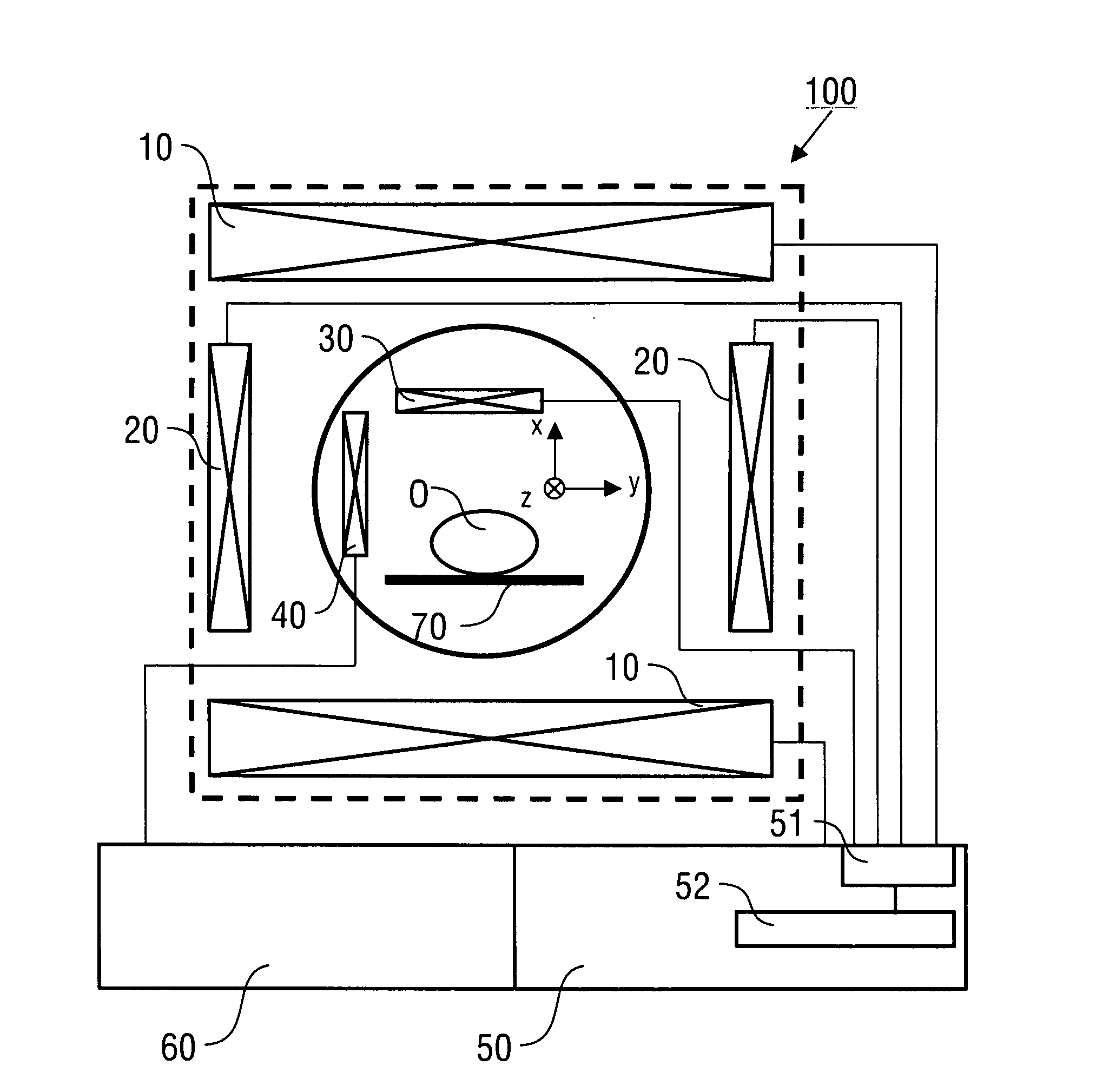
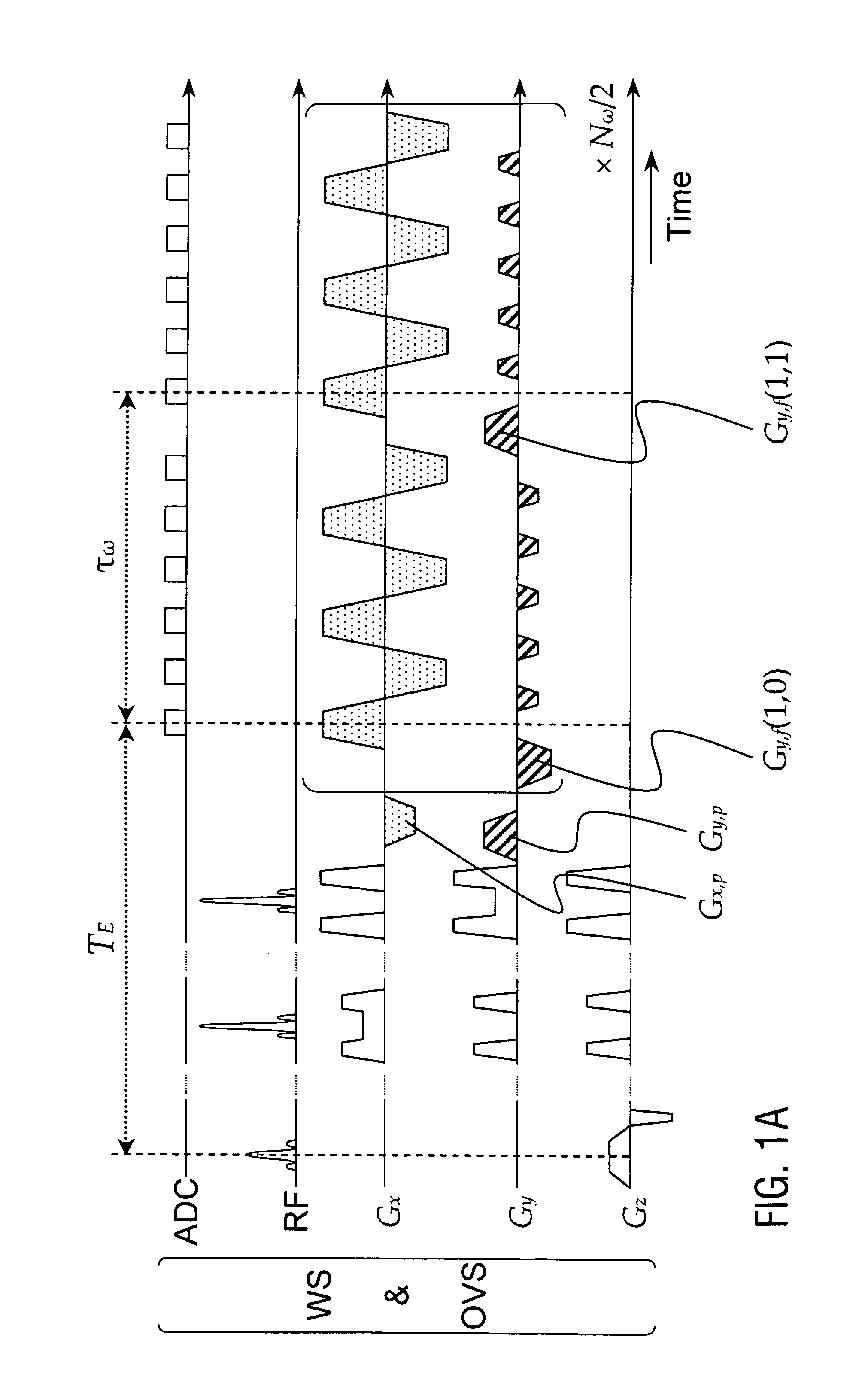
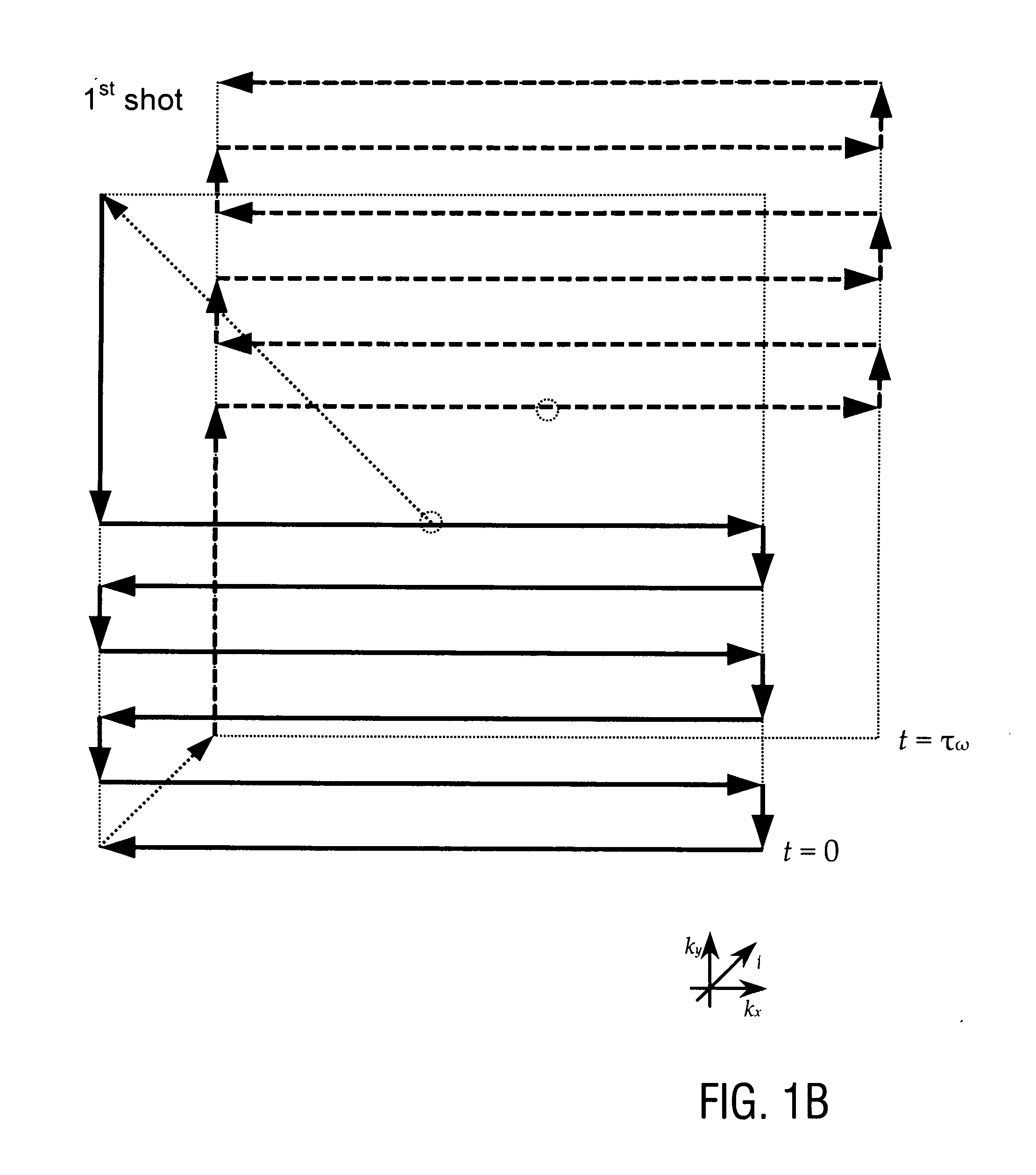
[0101]Preferred embodiments of the invention are described in the following with particular reference to the construction of the excitation and encoding sequences. Timing sequences are graphically represented as introduced in standard publications. Details of creating the RF pulses and gradients of these sequences, collecting the MR signals and controlling an MR scanner as well as details of the construction of an MR scanner are not described as far as they are known from PCT / EP 2009 / 002345 (introduced to the present specification by reference) or from conventional MR imaging techniques. Furthermore, after reconstructing the at least one spectroscopic image of the object, the image can be subjected to a further image processing or image recording, displaying, storing, or printing as it is known in prior art.

SCEPSIS Method

[0102]FIG. 1 shows a basic RF and gradient pulse sequence diagram of the first sampling sequence (FIG. 1A) and the corresponding first sampling trajectories in k-sp...


PUM


Abstract

A method of magnetic resonance spectroscopic imaging of an object (O) including at least one chemical species to be imaged, comprising sampling of the k-space such that a plurality of Nω first sampling trajectories through at least one k-space segment of the k-space is formed along a phase-encoding direction, each of said first sampling trajectories beginning in a central k-space region and continuing to a k-space border of the at least one k-space segment and having a duration equal to or below a spectral dwell time corresponding to the reciprocal spectral bandwidth, collecting at least one first set of gradient-echo signals obtained along said first sampling trajectories, collecting at least one second set of gradient-echo signals obtained along a plurality of Nω second sampling trajectories, said Nω second sampling trajectories and said Nω first sampling trajectories being mutually mirrored relative to a predetermined k-space line in the central k-space region.

Description

TECHNICAL FIELD[0001]The present invention relates to a method of magnetic resonance spectroscopic (MRS) imaging of an object, in particular to an MRS imaging (MRSI) method with improved imaging contrast and / or shortened acquisition time. Furthermore, the invention relates to an MRSI device adapted for implementing the MRI method. Preferred applications of the invention are in the field of biomedical MRSI.TECHNICAL BACKGROUND[0002]In the present specification, reference is made to the following publications cited for illustrating prior art techniques, in particular conventional MRS imaging, and conventional implementations of certain procedural measures or partial aspects of excitation and encoding sequences.[0003][1] R. V. Mulkern, L. P. Panych. Echo planar spectroscopic imaging. Concepts Magn. Reson. 13: 213-237 (2001).[0004][2] T. R. Brown, B. M. Kincaid, K. Ugurbil. NMR chemical shift imaging in three dimensions. Proc. Natl. Acad. Sci. USA 79: 3523-3526 (1982).[0005][3] A. A. Ma...

Claims


Application Information

Patent Timeline
IPC IPC(8): G01R33/56G01R33/34
CPCG01R33/4818G01R33/482G01R33/5616G01R33/5611G01R33/485
Inventor LABADIE, CHRISTIANHETZER, STEFANMILDNER, TORALFMOELLER, HARALD
Owner MAX PLANCK GESELLSCHAFT ZUR FOERDERUNG DER WISSENSCHAFTEN EV
Learn More