Ceramic honeycomb structure and its production method

Active Publication Date: 2012-12-20
HITACHI METALS LTD
View PDF5 Cites 16 Cited by
  • Summary
  • Abstract
  • Description
  • Claims
  • Application Information

AI Technical Summary

Benefits of technology

[0017]Accordingly, an object of the present invention is to solve the problems of the above conventional technologies, providing a ceramic honeycomb structure effectively capturing nano-particles dominant in terms of number in particles discharged, even in an initial stage of the use of a ceramic honeycomb filter in w

Problems solved by technology

An exhaust gas discharged from diesel engines contains particulate matter (PM) comprising as main components carbonaceous soot and soluble organic fractions (SOFs) comprising high-boiling-point hydrocarbon components, which are likely to adversely affect humans and environment when discharged into the air.
PM continuously captured by the cell walls 2 clogs communicating pores on and in the cell walls 2, resulting in increased pressure loss when the exhaust gas passes through the ceramic honeycomb filter.
However, because these requirements are in a contradictory relation, the optimization of porosity, pore volume, the size of pores on the cell wall surface, etc. have conventionally been investigated to meet both requirements.
Also, because nano-particles have larger surface areas per volume, toxic chemical substances adsorbed onto their surfaces likely make PM particles more toxic.
Because the amount of nano-particles in PM is small in terms of weight, current PM weight regulations do not work well.
However, the exhaust-ga

Method used


Image

  • Ceramic honeycomb structure and its production method
  • Ceramic honeycomb structure and its production method
  • Ceramic honeycomb structure and its production method

Examples


Example

Examples 1-24 and Comparative Examples 1-6

[0114]Silica powder, kaolin powder, talc powder, alumina powder and aluminum hydroxide powder having particle shapes (particle sizes, particle size distributions, etc.) and impurities shown in Tables 1-4 were mixed in the formulations shown in Table 6, to obtain cordierite-forming material powders having a chemical composition comprising 50% by mass of SiO2, 36% by mass of Al2O3 and 14% by mass of MgO. The amounts of ceramic materials shown in Table 6 are normalized such that the total amount of ceramic materials (including talc or silica contained in the pore-forming materials) is 100 parts by mass. Each of these cordierite-forming material powders was mixed with a pore-forming material having the particle shape shown in Table 5 in the amount shown in Table 6. After adding methylcellulose, the resultant mixture was blended with water to prepare a moldable ceramic material composed of cordierite-forming materials. Other pore-forming material...

Example

Example 25

[0118]32.0 parts by mass of titania powder having a median diameter of 1.6 μm, 56.1 parts by mass of alumina powder having a median diameter of 5 μm, 3.0 parts by mass of silica powder having a median diameter of 20 μm, and 3.0 parts by mass of magnesia powder having a median diameter of 2 μm as ceramic material powders having an aluminum titanate composition, a molding aid, and 7.0 parts by mass of titanium-oxide-coated, hollow resin particles having a median diameter of 20 μm and sphericity of 0.92 as a pore-forming material were mixed, blended, and extruded to obtain a honeycomb structure molding having an outer diameter of 50 mm, a length of 90 mm, a cell wall thickness of 10 mil (0.25 mm), and a cell density of 300 cpsi (46.5 cells / cm2). After drying, the molding was machined to remove its peripheral portions, and sintered by a schedule comprising temperature elevation at a heating speed of 50° C. / hour from room temperature to 150° C., at a heating speed of 10° C. / hou...


PUM

PropertyMeasurementUnit
Temperatureaaaaaaaaaa
Lengthaaaaaaaaaa

Abstract

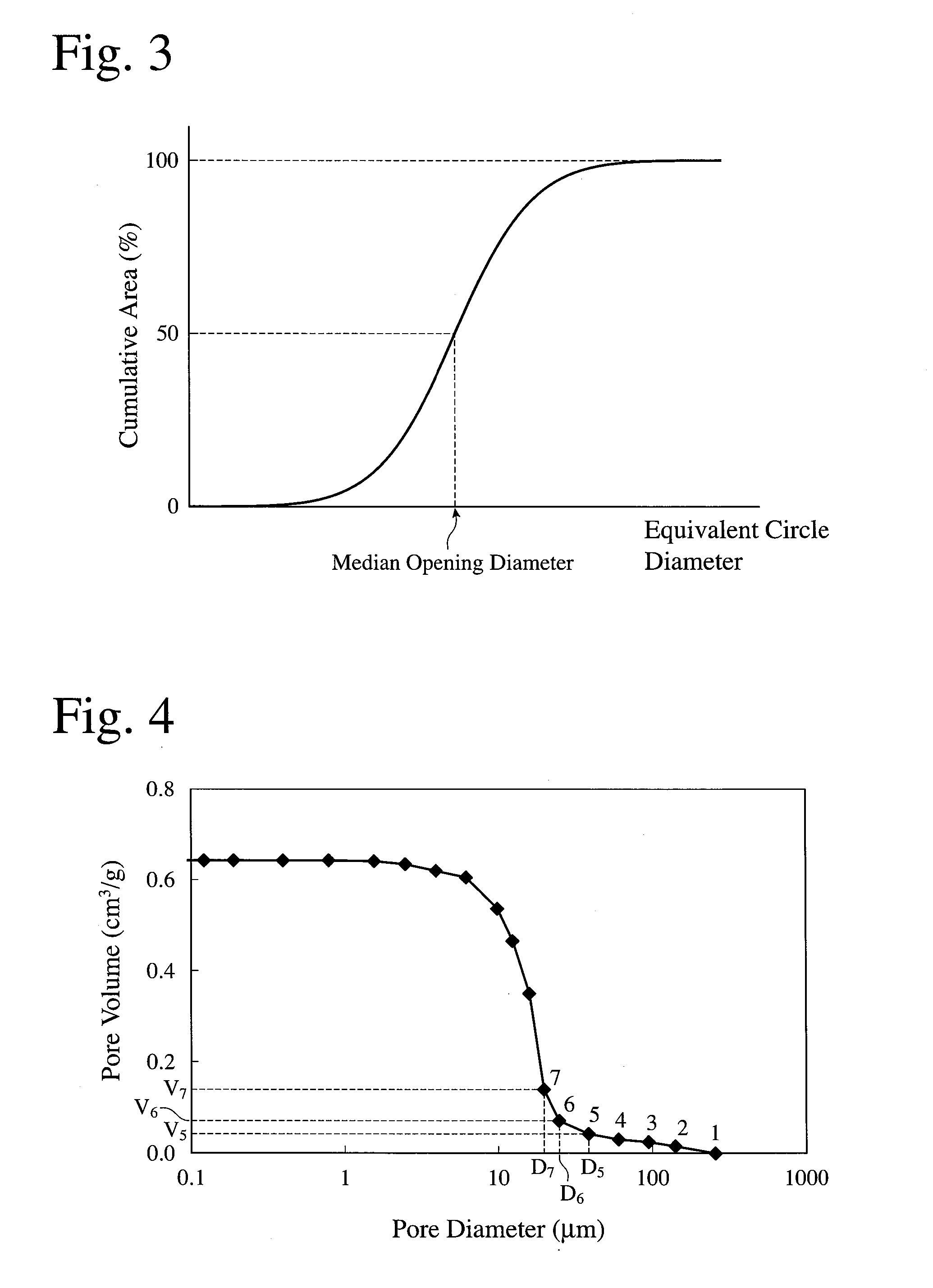
A ceramic honeycomb structure having a large number of flow paths partitioned by porous cell walls, the cell walls meeting the conditions; (a) the cell walls having porosity of 55-80%, (b) the cell walls having a median pore diameter D50 (measured by mercury porosimetry) of 5-27 μm, (c) pores open on cell wall surfaces having an opening area ratio of 20% or more, (d) pores open on cell wall surfaces having a median opening diameter d50 (determined from equivalent circle diameters on an area basis) of 10-45 μm, (e) the density of pores open on cell wall surfaces having equivalent circle diameters of 10 μm or more and less than 40 μm being 350/mm2 or more, (f) the maximum inclination of a curve of a cumulative pore volume relative to a pore diameter (determined from a pore distribution measured by mercury porosimetry) being 1.6 or more, and (g) a ratio D50/d50 of the median pore diameter D50 to the median opening diameter d50 being 0.65 or less.

Description

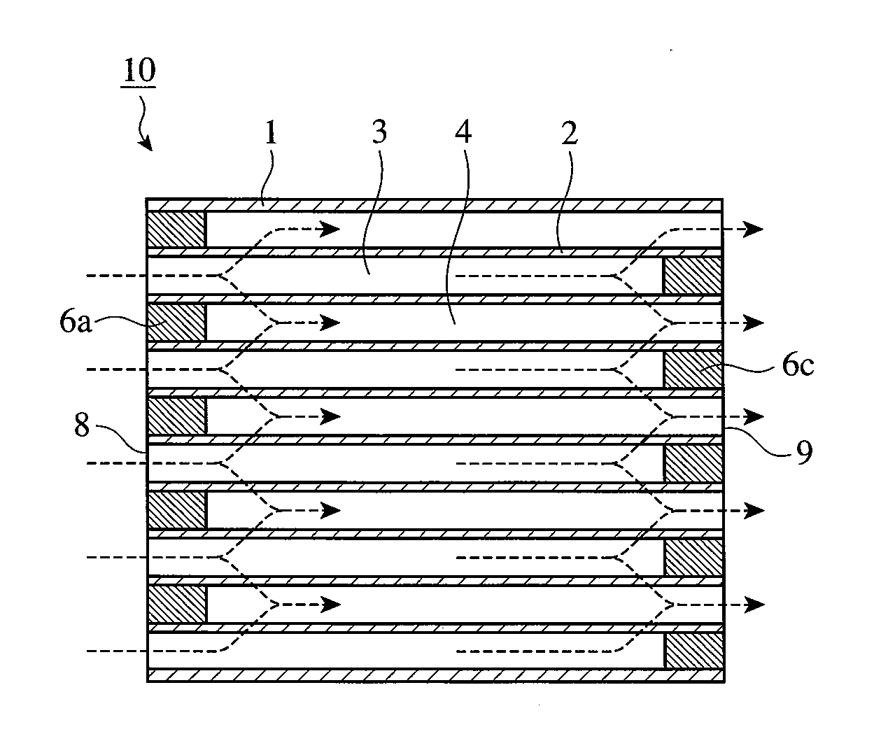
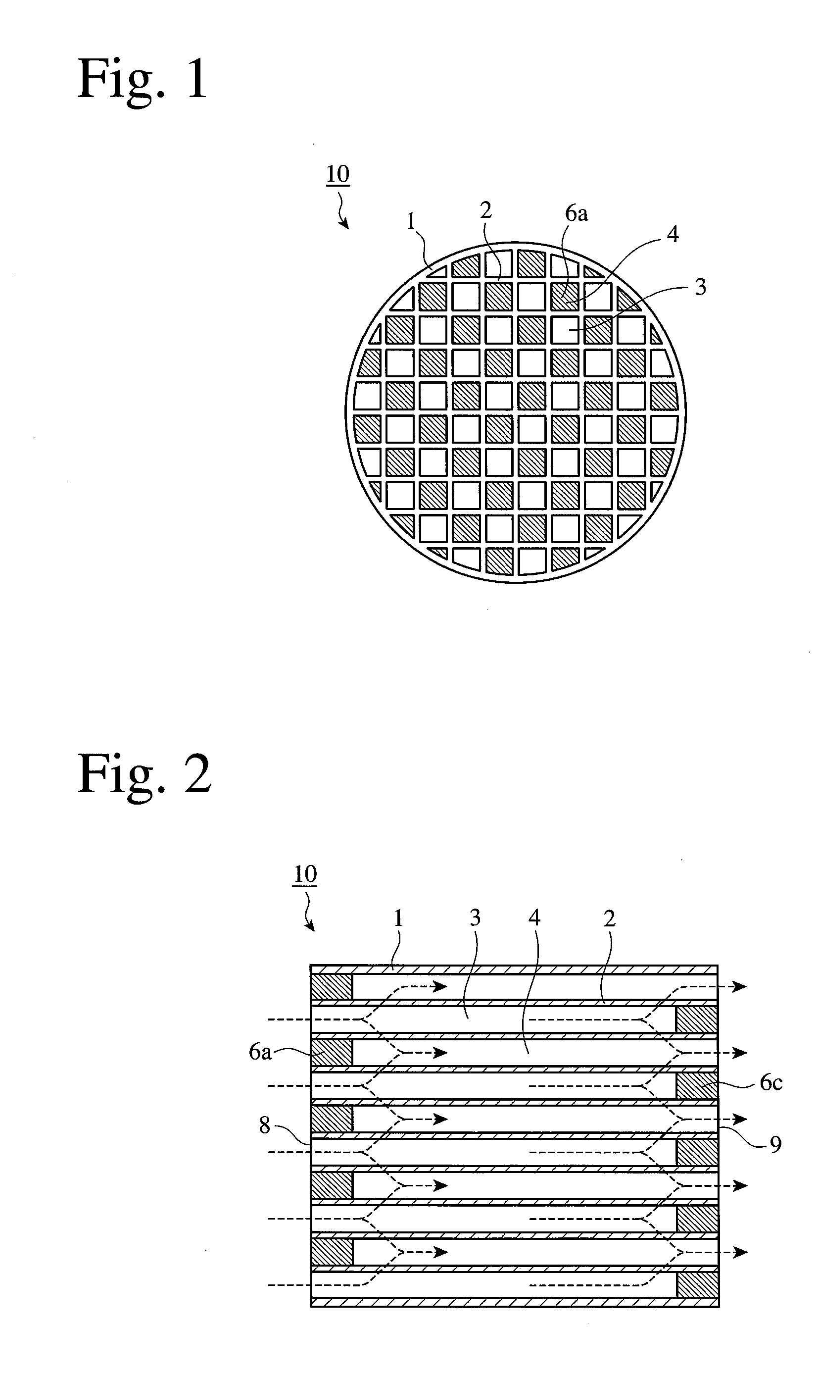
FIELD OF THE INVENTION[0001]The present invention relates to a ceramic honeycomb structure for constituting a ceramic honeycomb filter for removing particulate matter from exhaust gases discharged from diesel engines.BACKGROUND OF THE INVENTION[0002]An exhaust gas discharged from diesel engines contains particulate matter (PM) comprising as main components carbonaceous soot and soluble organic fractions (SOFs) comprising high-boiling-point hydrocarbon components, which are likely to adversely affect humans and environment when discharged into the air. Accordingly, ceramic honeycomb filters have conventionally been attached to exhaust pipes of diesel engines for removing PM.[0003]One example of ceramic honeycomb filters for capturing PM in the exhaust gas is shown in FIGS. 1 and 2. A ceramic honeycomb filter 10 comprises a ceramic honeycomb structure comprising porous cell walls 2 defining a large number of outlet-side-sealed flow paths 3 and inlet-side-sealed flow paths 4 and a peri...

Claims


Application Information

Patent Timeline
IPC IPC(8): B01D39/20B29C47/88B29C48/11
CPCB01D2239/1216B01D46/2444C04B38/0006F01N3/0222F01N2330/06B01D2239/125B01D2046/2437B01D2046/2433B01D46/2429Y02T10/20B01D2279/30C04B35/00C04B38/0054C04B38/0074C04B35/195C04B35/478C04B2235/3206C04B2235/3217C04B2235/3218C04B2235/3232C04B2235/3418C04B2235/349C04B2235/5296C04B2235/5436C04B2235/5445C04B2235/6021C04B2235/6562C04B2235/6565C04B2235/6567C04B2235/9607C04B41/85C04B41/009C04B41/5089C04B2111/00793B29C48/11B29C48/913Y02T10/12B01D46/24492B01D46/24491B01D46/24494C04B41/5035B01D39/20B01D46/2474B01D46/2484F02M35/02475B01D46/2425
Inventor OKAZAKI, SHUNJI
Owner HITACHI METALS LTD
Why Eureka
Try Eureka