
Method for producing hydrogen aimed at storage and transportation

a hydrogen and storage technology, applied in the direction of metal/metal-oxide/metal-hydroxide catalysts, physical/chemical process catalysts, sustainable manufacturing/processing, etc., can solve the problems of large amount of carbon monoxide and inevitably discharge of carbon dioxide (cosub>2/sub>), and achieve low cost, industrially produced efficiently, and the effect of smooth organic chemical hydride production

Active Publication Date: 2012-12-20
CHIYODA CORP
View PDF11 Cites 13 Cited by
  • Summary
  • Abstract
  • Description
  • Claims
  • Application Information

AI Technical Summary

Benefits of technology

[0020]Thus, the present invention provides a method producing hydrogen aimed at storage and transportation, by which hydrogen for storage and transportation that is necessary for smoothly performing an organic chemical hydride method can be industrially produced efficiently at low cost.
[0032]According to the method for producing hydrogen for storage and transportation of the present invention, hydrogen for storage and transportation that is necessary for smoothly performing an organic chemical hydride method can be industrially produced efficiently at low cost.

Problems solved by technology

The former, the on-site hydrogen station, involves a problem in that a large amount of carbon monoxide (CO) is produced as a by-product in the hydrogen production and a considerable amount of carbon dioxide (CO2) is inevitably discharged eventually.
In addition, when hydrogen is produced by those reforming reactions, a synthesis gas produced by the reforming reactions includes a large amount of carbon monoxide.
However, a large amount of nitrogen is necessary for the hydrogenation process at a large scale, and when excessive nitrogen is not available, an apparatus for producing nitrogen is required to be provided next to a hydrogenation reaction apparatus.

Method used


Image

  • Method for producing hydrogen aimed at storage and transportation
  • Method for producing hydrogen aimed at storage and transportation

Examples


first embodiment

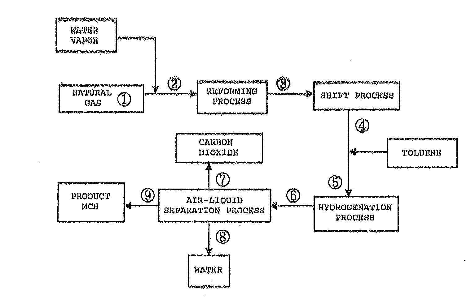
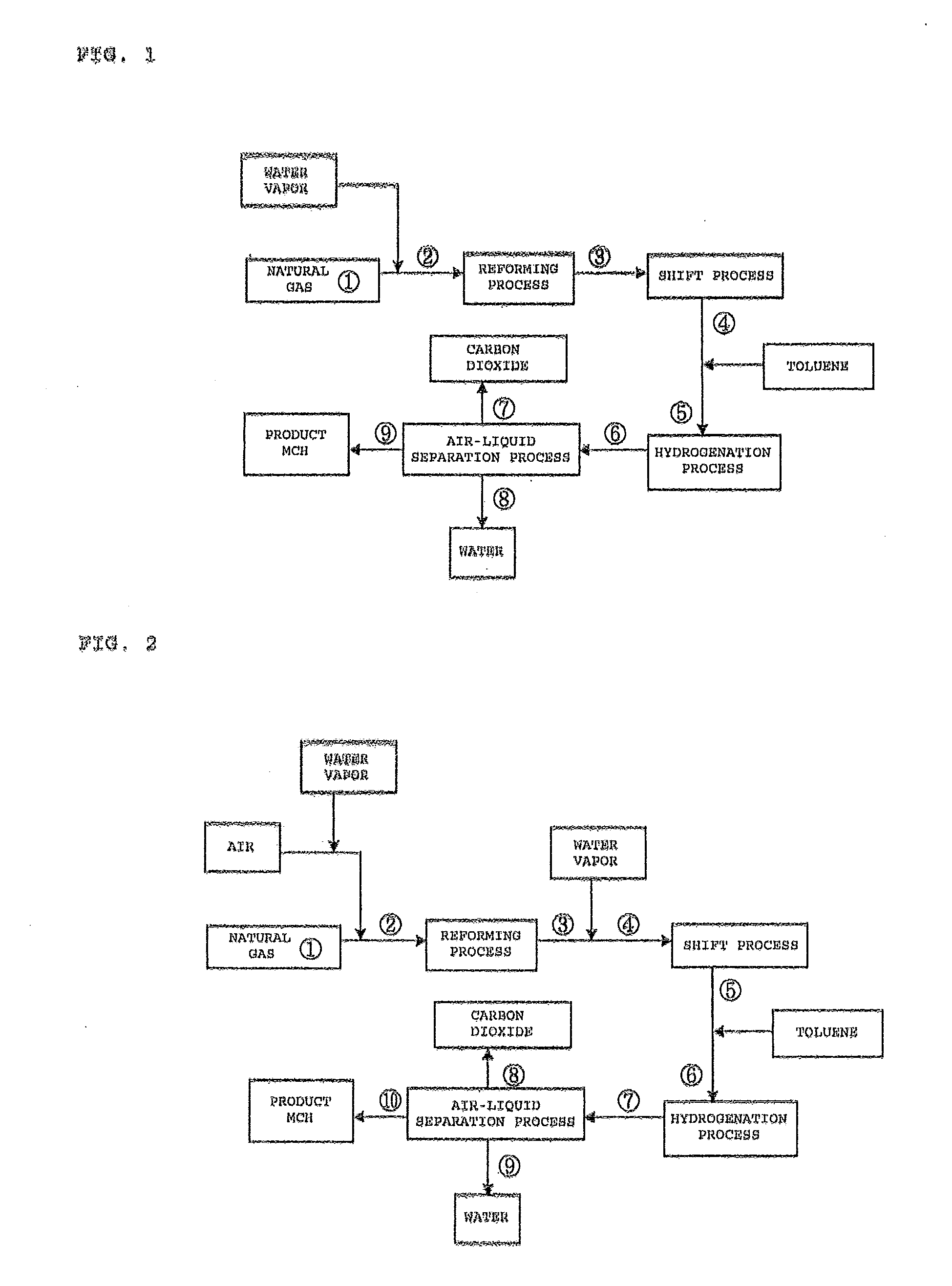
[0037]FIG. 1 illustrates a process flow of the case in which a steam reforming reaction is adopted as the reforming reaction according to the first embodiment of the present invention.

[0038]In the process flow of FIG. 1, the reaction conditions of a reforming reaction in the process were set to 900° C. and 2.15 MPaG, the reaction conditions of a shift reaction in the shift process were set to 250° C. and 2.0 MPaG, and further the reaction conditions of a hydrogenation reaction in the hydrogenation process were set to 250° C. and 1.9 MPaG. Then, a mass balance simulation at each point in the process flow was carried out. Results are shown in Table 1 described below.

TABLE 1Stream No.123456789Reaction40515900250250250404040temperature(° C.)Pressure2.152.152.002.001.901.901.851.851.85(MPaG)Mass balance(NM3 / H)H23.13.1316.4384.1384.171.069.20.11.8CO0.00.072.34.64.60.00.00.00.0CO20.00.027.495.195.195.183.10.411.7N20.90.90.90.90.90.90.90.00.9CH492.592.513.413.413.418.117.50.00.6C2H63.73.70....

second embodiment

[0039]FIG. 2 illustrates a process flow of the case in which a partial oxidation reforming reaction is adopted as the reforming reaction according to the second embodiment of the present invention.

[0040]In the process flow of FIG. 1, the reaction conditions of a reforming reaction in the reforming process were set to 1,050° C. and 2.15 MPaG, the reaction conditions of a shift reaction in the shift process were set to 250° C. and 2.0 MPaG, and further the reaction conditions of a hydrogenation reaction in the hydrogenation process were set to 250° C. and 1.9 MPaG. Then, a mass balance simulation at each point in the process flow was carried out. Results are shown in Table 2 described below.

TABLE 2Stream No.12345678910Reaction405151,050250250250250404040temperature(° C.)Pressure2.152.152.002.002.001.911.911.851.851.85(MPaG)Mass balance(NM3 / H)H23.723.75253.3253.3367.1367.165.164.50.010.54CO0.000.00117.2117.23.343.340.000.000.000.00CO20.000.1117.617.6131.5131.5131.5125.40.355.72N20.1129...

example 1

[0042]In order to verify the results of the simulation of the first embodiment, a simulated material having the composition shown in Stream No. 5 of FIG. 1 and Stream No. 5 in the item “Stream No.” in Table 1 (5 in a circle in FIG. 1 and Table 1) was used to carry out a hydrogenation reaction test. An Ni-supported silica-alumina catalyst commercially available for a hydrogenation reaction was used as a catalyst. 10 cc of the catalyst were filled in a reaction tube in a flow-type reaction tester. The pressure of the reaction tube was raised to 2.0 MPa under hydrogen flow. Further, the temperature of a catalyst layer was raised to 400° C., and this state was kept for 3 hours to carry out the preliminary reduction of the catalyst. Then, the temperature of the catalyst layer was lowered to 220° C. under nitrogen flow, and nitrogen was replaced by a simulated material gas. At this time, the simulated material gas, which had a composition of 67% of hydrogen, 1.0% of carbon monoxide, 17.0%...


PUM

PropertyMeasurementUnit
temperatureaaaaaaaaaa

Abstract

Provided is a method for producing hydrogen aimed at storage and transportation, by which hydrogen for storage and transportation that is necessary for smoothly performing an organic chemical hydride method can be industrially produced efficiently at low cost. The method is a method for producing hydrogen aimed at storage and transportation in an organic chemical hydride method, in which: the hydrogenation process of an aromatic compound uses, as a hydrogen source for the reaction of the aromatic compound, a reaction gas is produced by a reforming reaction and adjusted a hydrogen concentration from 30 to 70 vol % by a shift reaction; and a hydrogenated aromatic compound is separated from a reaction mixture obtained in the hydrogenation process, which is followed by purification.

Description

BACKGROUND OF THE INVENTION[0001]1. Field of the Invention[0002]The present invention relates to a method for producing hydrogen aimed at storage and transportation having a form which is suitable for storage and transportation, in particular, a method for producing hydrogen aimed at storage and transportation with a hydrogenated aromatic compound (organic chemical hydride) produced efficiently at low cost in the organic chemical hydride method, the hydrogenated aromatic compound serving as a hydrogen carrier suitable for bulk storage of hydrogen and / or long distance transportation of hydrogen.[0003]2. Description of the Related Art[0004]In recent years, emission control of carbon dioxide, which is a greenhouse gas, has been gaining momentum. As a result, progress has been made in developing and practically applying hydrogen energy application technologies, which are used for stationary fuel cells, hydrogen vehicles, fuel cell vehicles, and the like. Development has been made intens...

Claims


Application Information

Patent Timeline
Patent Type & Authority Applications(United States)
IPC IPC(8): C01B3/02C01B3/26
CPCB01J21/12B01J23/755C01B3/0015C01B3/32C01B2203/0283C01B2203/0415C01B2203/043C01B2203/0445C01B2203/0475H01M8/04216H01M8/0618Y02E60/328F17C11/005H01M8/065Y02E60/321Y02P30/30Y02E60/32Y02P30/00Y02E60/50
Inventor OKADA, YOSHIMISAITO, MASASHIWAKAMATSU, SHUHEISHIMURA, MITSUNORI
Owner CHIYODA CORP
Learn More