
Dump truck

a technology for dump trucks and trucks, applied in the field of dump trucks, to achieve the effect of reducing time lag, preventing one-sided brake operations, and effectively preventing fir

Active Publication Date: 2012-12-27
KOMATSU LTD
View PDF8 Cites 1 Cited by
  • Summary
  • Abstract
  • Description
  • Claims
  • Application Information

AI Technical Summary

Benefits of technology

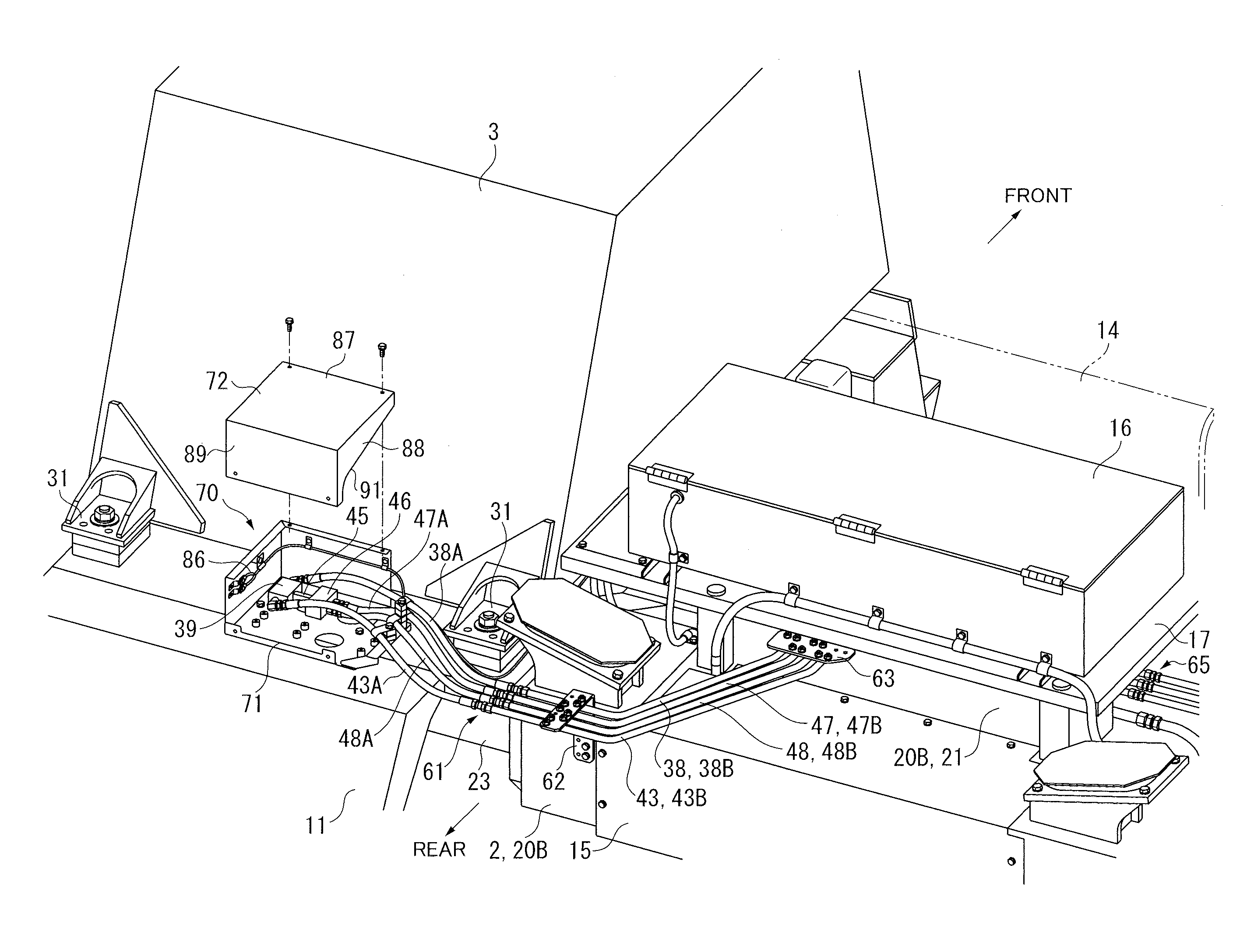
[0015]According to the first aspect of the invention, brake hydraulic devices (e.g. separating block) are offset from the middle of the vehicle body frame in the vehicle width direction, and the brake hydraulic devices are consequently not located above devices of high temperatures (e.g. exhaust pipe, exhaust turbocharger and engine) and a protective cover that covers the devices, so that the hydraulic oil blown out from the brake hydraulic device does not fall over the devices of high temperatures. Hence, a conventional complicated fire-prevention structure can be made unnecessary.
[0016]Further, the hydraulic lines that connect the separating block and the service brakes run through approximately the middle of the vehicle body frame in the vehicle width direction and are installed in a row, so that the hydraulic lines for both right-side and left-side service brakes can be made substantially identical in length, thus reducing a time lag between each of the service brakes until braking force is generated by each of the service brakes, thereby preventing one-sided brake operations.
[0017]According to the second aspect of the invention, no devices and portions of high temperatures but wheels and other portions are disposed below the cab that is arranged near an end of the vehicle body frame in the vehicle width direction. Hence, by disposing the separating block at the rear of the cab, even in an unlikely event of leaking the hydraulic oil from the separating block, the hydraulic oil does not fall over devices of high temperatures and the like, thus effectively preventing fire.
[0018]According to the third aspect of the invention, since the hydraulic lines between the shuttle valve and the service brake valve and between the shuttle valve and the retarder control valve run through approximately the middle of the vehicle body frame in the vehicle width direction and are installed in a row, one-sided brake operations can be further effectively prevented.
[0019]According to the fourth to the sixth aspects of the invention, the brake device box houses hydraulic devices (e.g. shuttle valve, separating block, solenoid valve for an exhaust brake, ABS cancellation valve and ABS valve), so that hydraulic lines connecting the hydraulic devices as well as connectors of hydraulic lines can also be collectively arranged. The fire-prevention structure of the connectors can be provided by the protective cover and the like collectively covering the concentrated connectors, so that it is not necessary to provide individual fire-prevention structure and the like, thereby further simplifying the structure.
[0020]Furthermore, since the hydraulic devices are covered by the brake device box, not only an appearance but also weather resistance and durability of the hydraulic devices can be improved.

Problems solved by technology

However, since the hydraulic devices of a dump truck such as a separating block are disposed above an exhaust pipe of which temperature tends to become high, a complicated fire prevention structure is used that keeps hydraulic oil from spattering on the high-temperature exhaust pipe even when the hydraulic oil is blown out of a connection between the hydraulic devices and hydraulic pipe or out of a joint between the hydraulic pipes, in the same manner as the construction machine disclosed in Patent literature 1.

Method used


Image

  • Dump truck
  • Dump truck
  • Dump truck

Examples


Embodiment Construction

)

[0033]The following is a detailed description of an exemplary embodiment of the invention with reference to drawings.

[0034]It should be noted that “front”, “rear”, “right” and “left” directions in the following description refer to the same direction as the “front”, “rear”, “right” and “left” directions for an operator seated on a driver seat in a cab 3. Further, the left-right direction is the same as a vehicle-width direction. Furthermore, a direction of to the right and to the left means the same as a vehicle width direction.

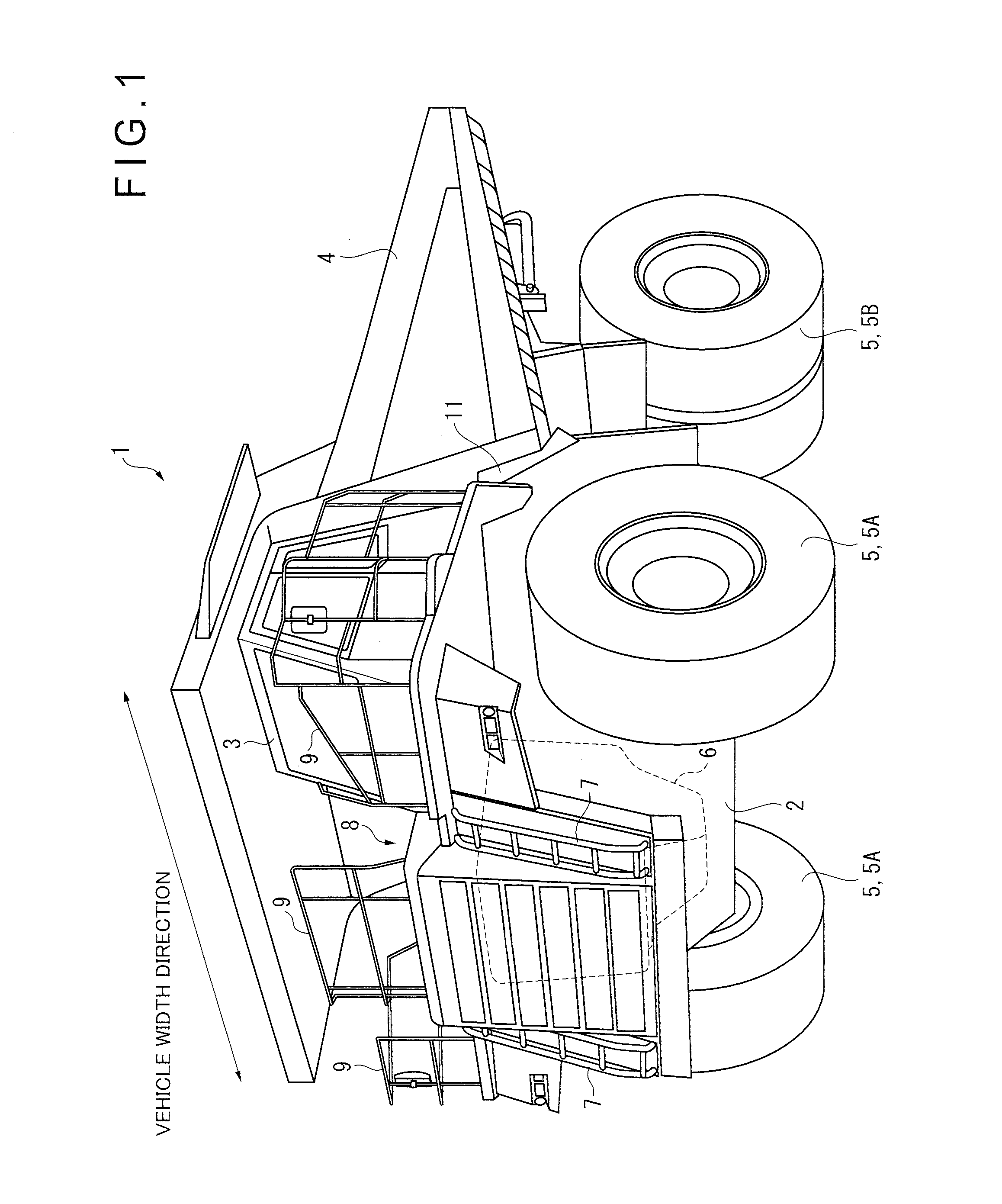
[0035]FIG. 1 is a perspective view that shows an entire dump truck 1 according to the exemplary embodiment of the invention.

[0036]In FIG. 1, the dump truck 1 that is large in size comprises a vehicle body frame 2. The cab 3 for a driver to be seated is installed at a left end of an upper front part of the vehicle body frame 2. A vessel 4 that carries loads (e.g. mined rocks and stones, and earth and sand) is provided at an upper rear part of the vehicle body...


PUM


Abstract

A dump truck is provided with service brakes provided on front wheels, and a separating block that separates and outputs hydraulic oil into each of the service brakes. The separating block is offset in a vehicle width direction from an exhaust pipe that is arranged substantially in a middle of the dump truck in the vehicle width direction. Hydraulic lines that connect the separating block and each of the service brakes are arranged to pass through the middle of the dump truck in the vehicle width direction, and are installed in a row between the separating block and the middle.

Description

TECHNICAL FIELD[0001]The invention relates to a dump truck, in particular to an improvement in an arrangement of a brake device box.BACKGROUND ART[0002]A protective cover for a large dump truck operating in a mine and other sites has been conventionally known. The protective cover that covers a rear part of an engine is attached to a portal frame that separates the engine and hydraulic piping provided along a vehicle frame in order to keep the pressure oil splattering from a damaged part from spattering over the engine when the hydraulic piping is damaged (See Patent Literature 1).[0003]The dump truck discharges exhaust gas from the engine through a vessel, in which the vessel is warmed by letting exhaust gas run though the vessel, resulting in an improvement in releasing earth, sand and the likes loaded in the vessel. Hence, an exhaust pipe for a passage of exhaust gas is disposed between the engine and the vessel.[0004]On the other hand, a braking system for the dump truck is conf...

Claims


Application Information

Patent Timeline
IPC IPC(8): B60T13/10B60T13/58B60T8/34
CPCB60T17/04B60T8/3685B60T8/3605B60T17/18
Inventor FURUKAWA, HIROYASU
Owner KOMATSU LTD
Learn More