Battery charging apparatus for electric vehicle

a charging apparatus and electric vehicle technology, applied in the direction of charging stations, electric vehicle charging technology, transportation and packaging, etc., can solve the problems of serious environmental pollution, global economic crisis, and use of fossil fuels, and achieve the effect of enhancing the reliability of connecting electronic components

Active Publication Date: 2012-12-27
DELTA ELECTRONICS (SHANGHAI) CO LTD
View PDF6 Cites 22 Cited by
  • Summary
  • Abstract
  • Description
  • Claims
  • Application Information

AI Technical Summary

Benefits of technology

[0007]The present invention provides a battery charging apparatus for an electric vehicle (EV) or a hybrid electric vehicle (HEV), in which the electronic components are electrically connected with the circuit board through conductive wires. Consequently, during the process of operating or running the electric vehicle or the hybrid electric vehicle, the possibility of damaging the electronic components arising from serious vibration will be reduced and the reliability of connecting the electronic components will be enhanced.
[0008]The present invention also provides a battery charging apparatus for an electric vehicle (EV) or a hybrid electric vehicle (HEV), in which the electronic component is fixed on the side plate or the bottom plate of the case chassis through a fixing member. In such way, the passive component body of the electronic component is securely fixed. Moreover, since the fixing member may provide a heat-transferring path and increase the contact area, the thermal resistance between the passive component body and the case chassis is reduced and the heat-dissipating efficacy is enhanced.
[0009]The present invention further provides a battery charging apparatus for an electric vehicle (EV) or a hybrid electric vehicle (HEV), in which the flexibility of the layout space within the battery charging apparatus is enhanced. In such way, the overall volume battery charging apparatus can be further reduced.
[0010]The present invention further provides a cooling mechanism of a battery charging apparatus for an electric vehicle (EV) or a hybrid electric vehicle (HEV), in which heat pipes are disposed on the fins of the cooling mechanism to increase the heat-dissipating efficacy. In addition, the cooling mechanism may include at least one fan for facilitating removing the heat from the fins. In such way, the cooling mechanism can effectively dissipate the heat of the battery charging apparatus, and the volume and cost of the cooling mechanism are both reduced.

Problems solved by technology

As known, burning fossil fuels causes serious environmental pollution.
In addition, fossil fuel depletion may lead to global economic crisis.
However, since it is necessary to burn gasoline during the operations of the gasoline-powered vehicles, the problems of using fossil fuels occur.
In the conventional charging system, many bulky and heavy electronic components (e.g. capacitors, inductors or transformers) are disposed on a system board.
Since the charging system is disposed within the electric vehicle or the hybrid electric vehicle, the charging system is usually suffered from vibration during the process of operating or running the electric vehicle or the hybrid electric vehicle.
If the vibration is too serious, the solder jointers of the electronic components of the charging system are readily broken due to the way of fixing the electronic components, soldering the pins to PWB only.
Under this circumstance, the charging system will have malfunction, and thus the maintenance cost will be increased.
If the heat fails to be effectively removed, the operating efficiency of the charging system is deteriorated, and the electronic components are possibly damaged.
Under this circumstance, the charging system fails to be normally operated.
However, the use of the air fails to effective remove the heat of the electronic components or the charging system.
In addition, since the flow-guiding structure may increase the overall volume of the charging system, the charging system fails to be minimized and the fabricating cost thereof is increased.

Method used


Image

  • Battery charging apparatus for electric vehicle
  • Battery charging apparatus for electric vehicle
  • Battery charging apparatus for electric vehicle

Examples


Embodiment Construction

[0030]The present invention will now be described more specifically with reference to the following embodiments. It is to be noted that the following descriptions of preferred embodiments of this invention are presented herein for purpose of illustration and description only. It is not intended to be exhaustive or to be limited to the precise form disclosed.

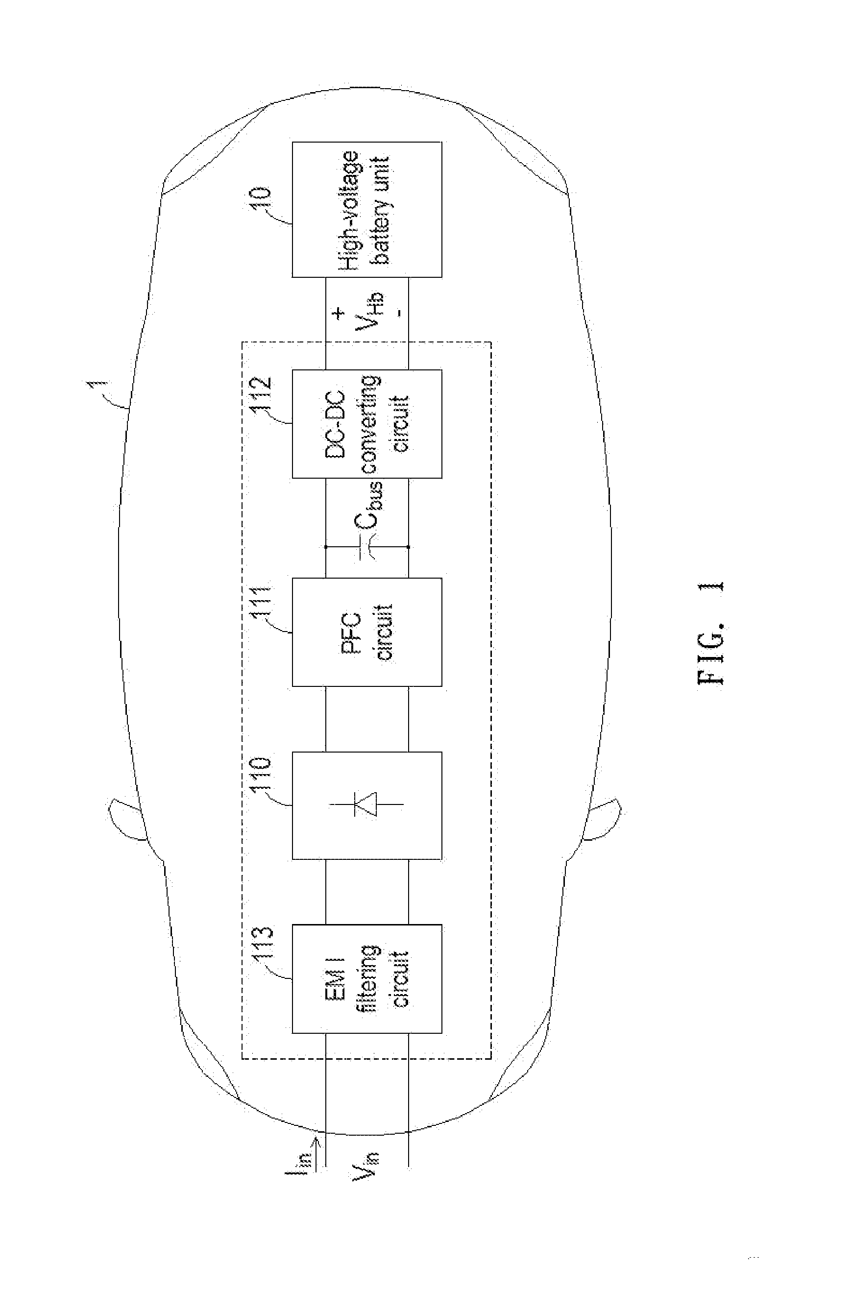
[0031]FIG. 1 is a schematic circuit block diagram illustrating the architecture of a battery charging apparatus for an electric vehicle according to an embodiment of the present invention. The battery charging apparatus is a high voltage battery charging apparatus installed in an electric vehicle body 1. The high voltage battery charging apparatus is used for receiving electric energy of an AC input voltage Vin from an utility power source, and charging a high-voltage battery unit 10. As shown in FIG. 1, the high voltage battery charging apparatus comprises a rectifier circuit 110, a power factor correction (PFC) circuit 111 and ...


PUM


Abstract

A battery charging apparatus for an electric vehicle (EV) or a hybrid electric vehicle (HEV) includes a case chassis, a circuit board and at least one electronic component. The case chassis includes a plurality of side plates, a bottom plate and a receptacle. The circuit board is accommodated within the receptacle of the case chassis. The electronic component includes a passive component body with a plurality of conductive wires and a fixing member for accommodating the passive component body. The conductive wires are electrically connected to the circuit board. The fixing member is fixed on at least one of the side plates and the bottom plate of the case chassis.

Description

FIELD OF THE INVENTION[0001]The present invention relates to a battery charging system for an electric vehicle (EV) or a hybrid electric vehicle (HEV), and more particularly to a battery charging system for EV or HEV in order to reduce the influence of shock and vibration and increase the heat-dissipating efficiency.BACKGROUND OF THE INVENTION[0002]Fossil fuels such as petroleum and coal are widely used in automobiles for generating motive force or electrical power. As known, burning fossil fuels causes serious environmental pollution. In addition, fossil fuel depletion may lead to global economic crisis. Gasoline-powered vehicles are widely used for transportation and become indispensable to our daily lives. However, since it is necessary to burn gasoline during the operations of the gasoline-powered vehicles, the problems of using fossil fuels occur.[0003]Consequently, there are growing demands on clean and renewable energy. Recently, electric vehicles (EV) and hybrid electric veh...

Claims


Application Information

Patent Timeline
Patent Type & Authority Applications(United States)
IPC IPC(8): H02J7/00
CPCB60L11/1812H02J7/0042Y02T90/127Y02T90/14Y02T10/7005B60L53/22Y02T10/70Y02T10/7072Y02T90/12
Inventor YOU, PEIAILIU, GANGZHANG, JINFA
Owner DELTA ELECTRONICS (SHANGHAI) CO LTD
Why Eureka
Try Eureka