
Resistance welding high frequency transformer and spot welding machine

a high-frequency transformer and spot welding technology, which is applied in the direction of transformer/inductance details, inductance, manufacturing tools, etc., can solve the problems of low duty rate, difficult to meet production needs, and difficult to output a large current at low voltage of high-frequency transformers, so as to reduce the leakage inductance and igbt stress requirements, reduce the volume of transformers, and improve the power and duty rate of transformers

Inactive Publication Date: 2013-01-10
SHENZHEN HONGBAI TECH IND
View PDF5 Cites 8 Cited by
  • Summary
  • Abstract
  • Description
  • Claims
  • Application Information

AI Technical Summary

Benefits of technology

"The present invention is a resistance welding high frequency transformer that increases the power of a single transformer, reduces the number of transformers connected in parallel, and reduces the volume of the transformer to improve its duty rate and reduce its leakage inductance. The transformer includes multiple sub-transformers with magnetic cores and primary and secondary coils that are placed on a circular cylinder. The secondary coil is cooled by water to reduce its size and improve its cooling efficiency. The transformer is designed to improve its power and duty rate, making it suitable for high power suspension spot welding machines. The technical effects of the invention include reducing the size and weight of the transformer, reducing the leakage inductance, and improving the duty rate and power factor of the transformer."

Problems solved by technology

However, due to electronic devices, materials of high frequency transformer and the limitations of production process, distribution parameters (capacitance, inductance, leakage inductance and loss) of high frequency transformer are increased and high frequency transformer is difficult to output a large current at low voltage, particularly, the duty rate is lower and can not meet the needs of production.
First, because the capacitance and inductance are too large and magnetic circuit is too long and the leakage inductance is intense, the expect stress of IGBT is too high.
Second, because the parameters of single transformer and the discreteness of performance, the prior art is difficult to use multiple transformers in parallel.
Third, because multiple power supplies are connected in parallel, taking sharing current technology, responding slowly, high cost, complex circuit, the prior art is difficult to meet the requirements of spot welding machine and the volume is too large.
Fourth, the loss of transformer is too large. The cooling of high frequency transformer is difficult. The duty rate is low.

Method used


Image

  • Resistance welding high frequency transformer and spot welding machine
  • Resistance welding high frequency transformer and spot welding machine
  • Resistance welding high frequency transformer and spot welding machine

Examples


Embodiment Construction

[0031]The present invention will be described in detail with reference to the figures and embodiments.

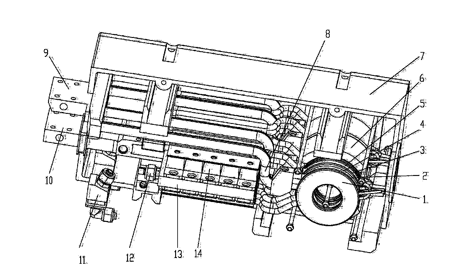
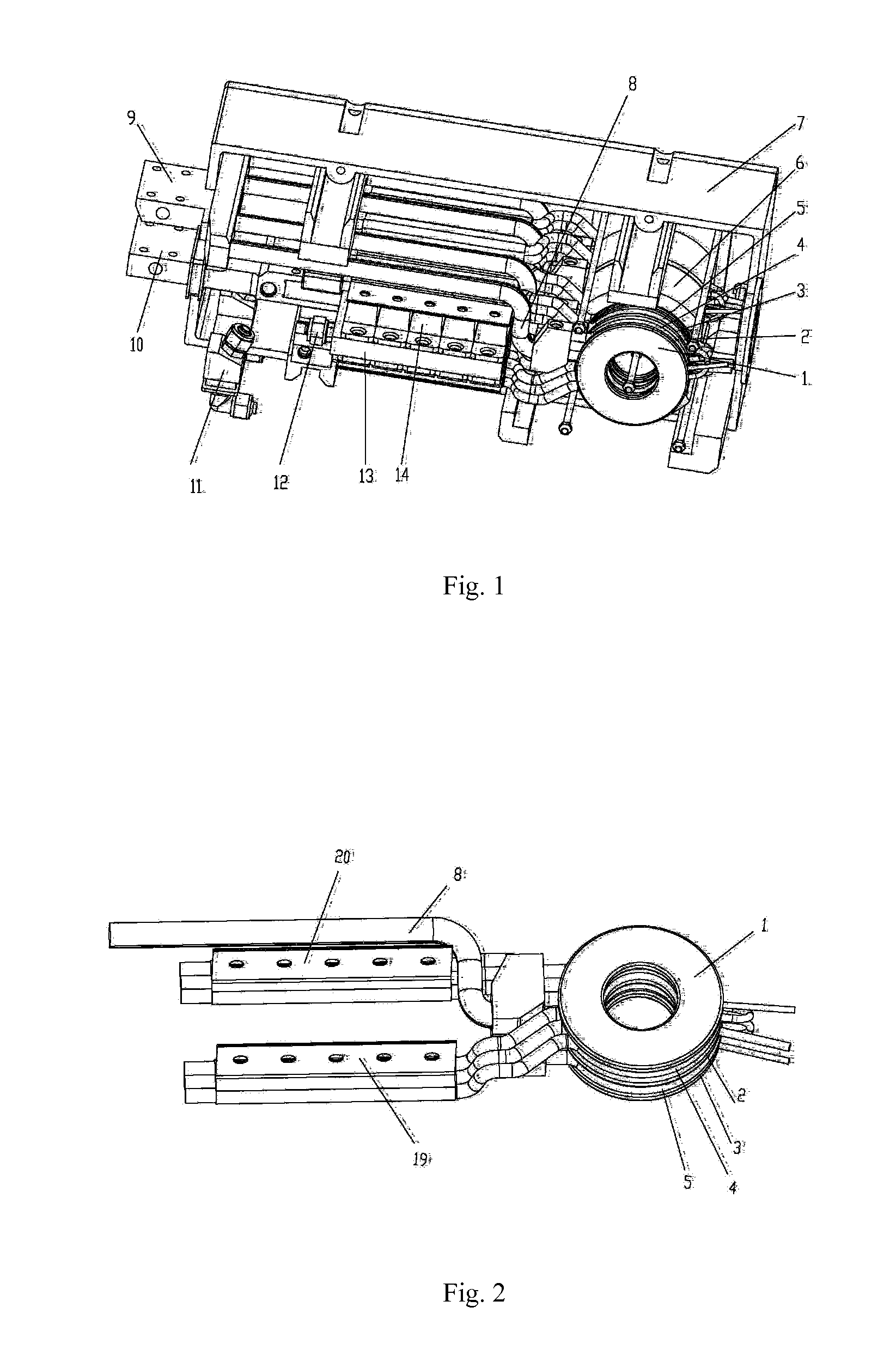
[0032]The working principle of the present invention is shown in FIG. 5. The said high frequency resistance welding transformer is composed of two sub-transformers. As shown in H unit, each sub-transformer is composed of two transformer units. As shown in J unit, each transformer unit is composed of three primary coils (as 2, 3 in FIG. 2) and two secondary coils (as 4, 5 in FIG. 2).

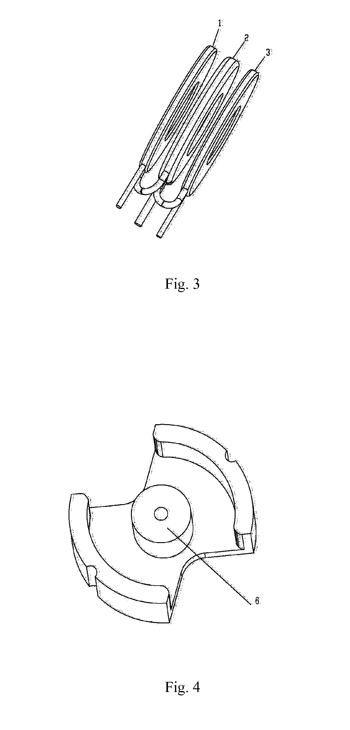
[0033]As shown in FIGS. 1, 2 and 4, wherein, 1 indicates B coil of the primary coil unit of the transformer. 2 indicate a coil of the primary coil unit of the transformer. 3 indicates B coil of the primary coil unit of the transformer. 4 indicates secondary coil. 5 indicate the secondary coil. 6 indicate the magnetic core. 7 indicate the former shell. 8 indicate the center tap of the sub-transformer. 9 indicates negative output terminal (i.e. the center tap of the transformer) of the transformer and recti...


PUM

PropertyMeasurementUnit
diameteraaaaaaaaaa
wall thicknessaaaaaaaaaa
diameteraaaaaaaaaa

Abstract

A resistance welding high frequency transformer and a high frequency resistance welding machine using the same are disclosed. The transformer comprises a magnetic core (6), primary coils (1, 2, 3) and secondary coils (4, 5). The primary coils and the secondary coils are alternatively positioned layer by layer. Each secondary coil is arranged between two primary coils. The primary coils are provided at the internal side and the external side of the secondary coil. The secondary coil is composed of red copper pipes through which water flows. Each secondary coil is wound with one to two turns. The red copper pipes of the secondary coils and rectifier diodes constitute a full-wave rectifier circuit. The resistance welding high frequency transformer can be wound conveniently. Its structure can reduce size, weight, leakage inductance and copper circuit loss, and the heat from the primary coils and secondary coils is dissipated conveniently, thus enabling the high-frequency transformer to output high current and high power with a high duty cycle. The resistance welding machine using the transformer has high power factor, high output power, small volume, light weight, and saves energy and material, which is especially suitable to produce a suspension spot welding machine with the integration of the transformer and welding tongs.

Description

TECHNICAL FIELD[0001]The present invention relates to a high frequency resistance welding transformer and a spot welding machine using the said transformer. The present invention is suitable for the high frequency inverter switch power supply and resistance welding power supply.BACKGROUND[0002]High frequency switch power supply technology is widely used in industry, agriculture and national defense currently, especially resistance welding, to reduce the volume of resistance welding machine and save an amount of copper. However, due to electronic devices, materials of high frequency transformer and the limitations of production process, distribution parameters (capacitance, inductance, leakage inductance and loss) of high frequency transformer are increased and high frequency transformer is difficult to output a large current at low voltage, particularly, the duty rate is lower and can not meet the needs of production. The disadvantages said above are mainly reflected in the followin...

Claims


Application Information

Patent Timeline
Patent Type & Authority Applications(United States)
IPC IPC(8): B23K11/24
CPCH01F27/2876H01F2027/408H01F38/085
Inventor HAN, YUQICHEN, ZHIWEIZHOU, YANGCHUNREN, ZAIXIANGLI, BAIJUNZHU, KONGCHEN
Owner SHENZHEN HONGBAI TECH IND
Learn More