Efficient water oxidation catalysts and methods of energy production

Inactive Publication Date: 2013-02-14
TOYOTA JIDOSHA KK
View PDF19 Cites 11 Cited by
  • Summary
  • Abstract
  • Description
  • Claims
  • Application Information

AI Technical Summary

Benefits of technology

[0005]The following summary of the invention is provided to facilitate an understanding of some of the innovative features unique to the present invention and is not intended t

Problems solved by technology
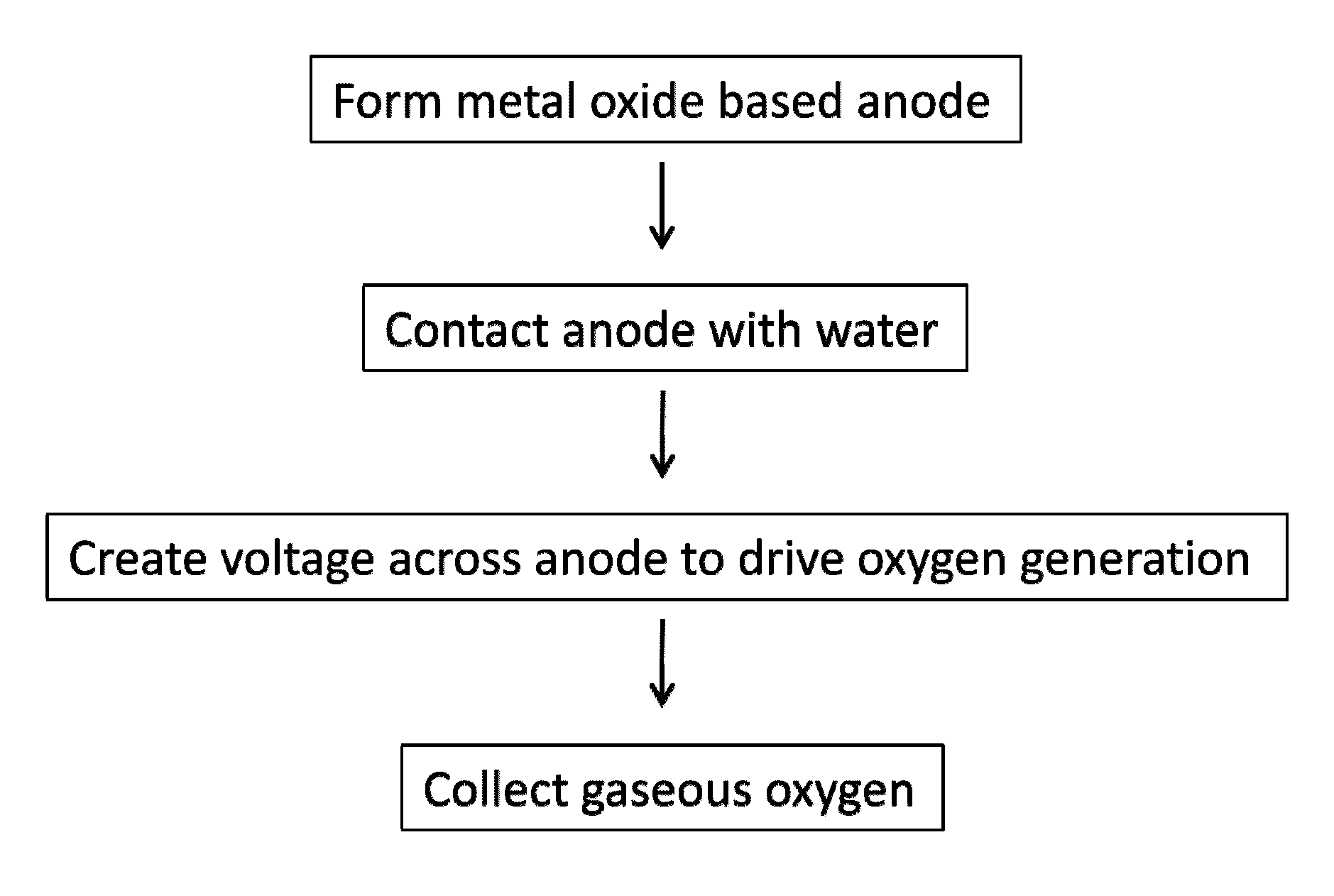
Fossil fuels may temporarily be capable of meeting the future increases in demand, but due to their link to increased concentrations of CO2 in atmosphere, continued use of fossil fuels is expected to result in unpredictable and possibly damaging climate changes.
Thus, alternative fuels or energy from clean resources are urgently needed.
One difficulty facing solar as a transpiration energy source is its requirement for robust incident sunlight.
Methods of storing solar en

Method used


Image

  • Efficient water oxidation catalysts and methods of energy production
  • Efficient water oxidation catalysts and methods of energy production
  • Efficient water oxidation catalysts and methods of energy production

Examples


example 1

Formation of a Co3O4 Catalytic Coating on a Cobalt Substrate

[0050]A cobalt foil sheet and cobalt wire is obtained from American Elements, Los Angeles, Calif. The cobalt foil or sheet is placed on the surface of a hotplate pre-heated to 350° C. exposed to air at ambient conditions for 6 hours. The formation of a layer of black oxide is observed on the metal surface. The formation of oxides are repeated with wires or foils of Fe, Cu, and Zn each with similar results.

[0051]The resulting Co3O4 / Co materials are characterized by SEM (scanning electron microscopy) for surface morphology, and by electrochemical measurement to verify catalytic activity for water oxidation. The surface morphology of the surface of a cobalt foil before heating and after heating is illustrated in FIG. 3. Heating in the presence of air produces wall-like structures with dimensions in nanometer range.

[0052]The Co wires (1 mm in diameter) are subjected to heating at 350° C. for up to 14 hours while the growth of n...

example 2

Cyclic Voltammetry

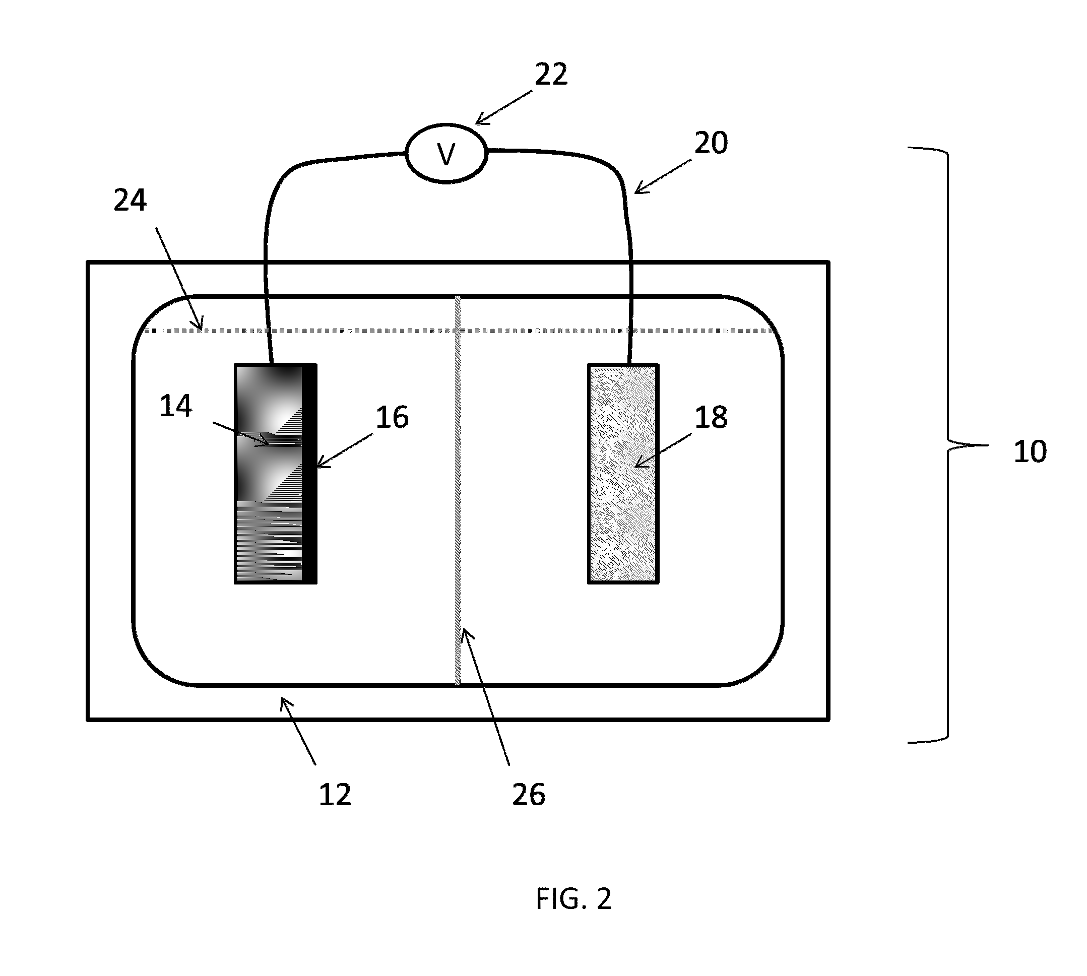
[0053]Cyclic voltammetry of the metal oxide based anodes of Example 1 are analyzed in a two chamber cell. As comparison, Pt is also studied as the working electrode. The electrolyte (pH 7.0, phosphate buffer) is purged thoroughly with argon prior to use. A voltage is applied to the electrode and scanned at different scan rates, typically in the range of 10-100 mV / s. CV analyses confirmed that, with similar physical dimensions (apparent surface area), Co wire / Co3O4 electrode provides much higher current density or much less over potential, as compared to Pt wire electrode. FIG. 5.

example 3

Oxygen Production at a Metal Oxide Based Anode

[0054]The electrochemical cell of Example 2 is used with an installed an optical oxygen sensor (OceanOptics, Inc., Dunedin, Fla.) next to the Co wire / Co3O4 electrode. The oxygen sensor is placed ˜2 mm over the Co wire / Co3O4 working electrode. The entire system is sealed from the environment using rubber septa in ground glass joints attached to the electrochemical cell housing and purged of air by bubbling with He gas (or other inert gas, e.g., N2, Ar). The working electrode is posed at 0.6, 0.8, 1.0, 1.2, 1.4 and 1.6 V vs. Ag / AgCl reference electrode for about 15 min under each of the applied potentials. The concentration of oxygen in the electrode is recorded continuously during each test. FIG. 6 illustrates that when the potential of the working electrode is ramped up from 0.6 to 1.6 V at 0.2 V intervals (15 min per step), significant oxygen formation is detected at 1.2 V vs. Ag / AgCl. The trend of the change of oxygen concentration als...


PUM


Abstract

Processes for the liberation of oxygen and hydrogen from water are provided allowing for mass scale production using abundant sources of catalyst materials. A metal oxide based anode is formed by the simple oxidation of metal in air by heating the metal for a specified time period. The resultant anode is then contacted with water and subjected to a voltage from an external source or driven by electromagnetic energy to produce oxygen at the surface of the anode by oxidation of water. These processes provide efficient and stable oxygen or hydrogen production.

Description

FIELD OF THE INVENTION[0001]This disclosure relates to efficient processes of water oxidation and catalysts that are readily formed, efficient, and commercially viable for large scale energy production or storage. Electrochemical devices are used herein for the catalytic formation of gaseous oxygen or hydrogen from water.BACKGROUND OF THE INVENTION[0002]The demand for transportation fuels is expected to increase dramatically in the next 50 years due to the current increases in population as well as improvements in the developing world. Fossil fuels supply more than 70% of current transportation energy consumption due to its ready availability and relatively inexpensive cost. Fossil fuels may temporarily be capable of meeting the future increases in demand, but due to their link to increased concentrations of CO2 in atmosphere, continued use of fossil fuels is expected to result in unpredictable and possibly damaging climate changes. Thus, alternative fuels or energy from clean resou...

Claims


Application Information

Patent Timeline
IPC IPC(8): C25B1/04C25B11/06
CPCC25B1/003Y02E60/368C02F2001/46138C02F1/4672C02F1/46109C25B1/55Y02E60/36
Inventor JIA, HONGFEIBANERJEE, DEBASISH
Owner TOYOTA JIDOSHA KK
Why Eureka
Try Eureka