Method for conversion of low temperature heat to electricity and cooling, and system therefore

a low temperature heat and electricity technology, applied in the field of low temperature heat conversion to electricity and cooling, can solve the problems of no thermodynamic cycle known to directly generate electricity, heat and cold, no efficient, convenient method available today, etc., to maximize competitiveness, minimize energy loss, and keep simple

Active Publication Date: 2013-02-14
CLIMEON AB
View PDF6 Cites 19 Cited by
  • Summary
  • Abstract
  • Description
  • Claims
  • Application Information

AI Technical Summary

Benefits of technology

[0018]In order to provide the most efficient energy conversion system, one would desire to minimize energy losses at all places in the energy cycle. In order to maximize the competitiveness, the system also needs to be kept simple, robust and avoiding cost driving conditions.

Problems solved by technology

However, no method is known how to operate such a process using heat sources which are considered of low value, i.e. in the range of 60-150° C., or 70-140° C., or 80-130° C. Further, no thermodynamic cycle has been disclosed which can directly generate electricity, heat and cold.
The main disadvantage of the known technology is thus that there is no efficient, convenient method available today which can produce energy in the form of electricity, heat and cold using heat sources today considered being of low value.
The methods known under the term ORC cycle are, despite a low thermal-to-electricity conversion efficiency, possibly useful in the temperature range starting from 130° C., but they cannot concurrently and directly provide energy in the form of cold.
In general, equipment and operational costs increase with pressure and temperature.
Also, the costs of providing hot media which can drive a thermodynamic cycle, increase with pressure and temperature.

Method used


Image

  • Method for conversion of low temperature heat to electricity and cooling, and system therefore
  • Method for conversion of low temperature heat to electricity and cooling, and system therefore
  • Method for conversion of low temperature heat to electricity and cooling, and system therefore

Examples


Embodiment Construction

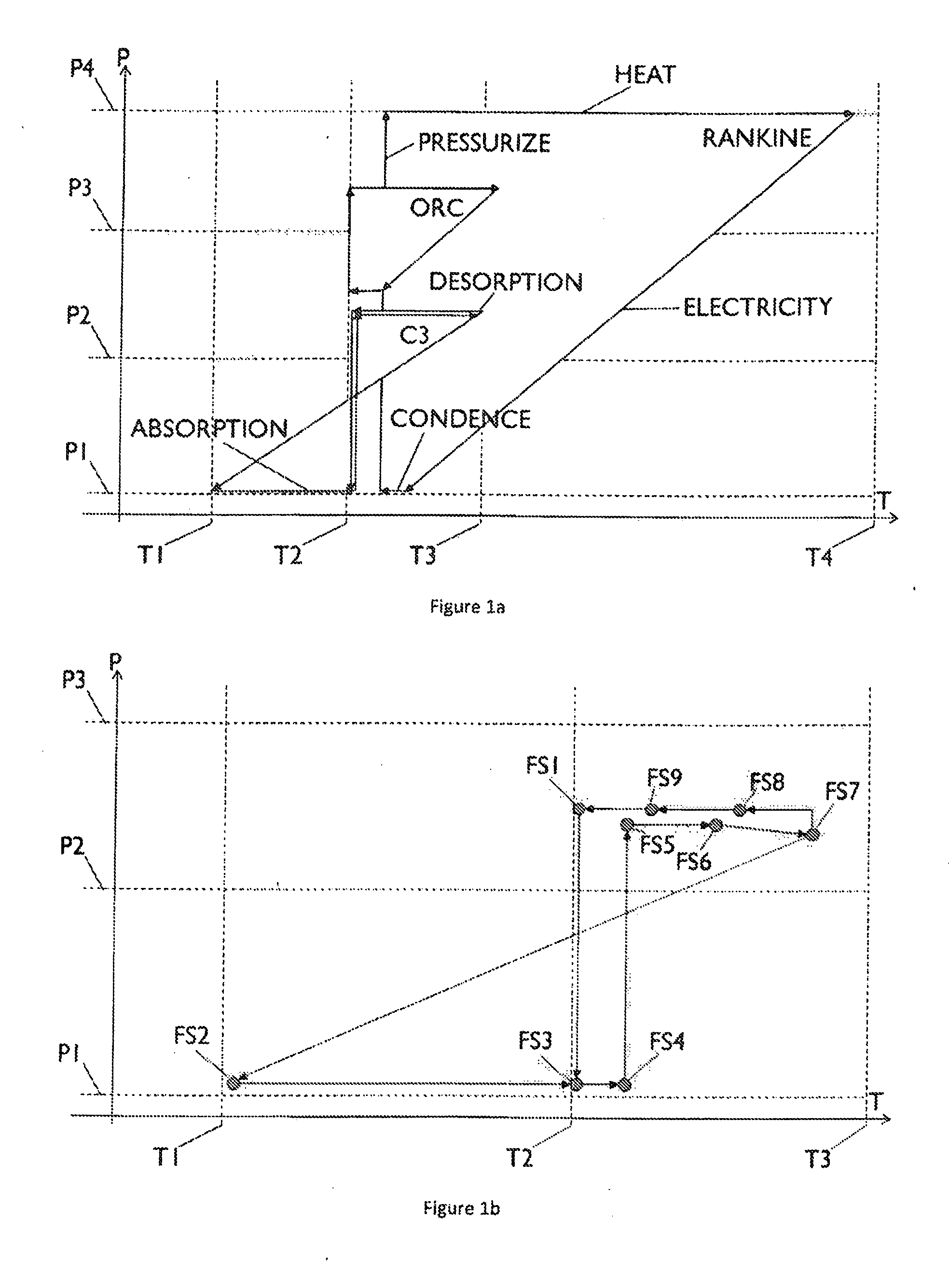
[0040]Referring now to the embodiment described in figure la, representing a generalized view of the Carbon carrier cycle with respect to other known power cycles from a pressure versus temperature perspective.

[0041]The Rankine cycle or steam cycle as described works by pressurizing and heat water to produce steam. Electricity is produced by expanding the steam from this point with P4 at typically 100 Bar and T4 at 500° C. down to below 100° C. where it is condensed back to water during cooling creating a low pressure close to vacuum.

[0042]The low temperature cycle named Organic Rankine Cycle, ORC, uses the same principle but, instead of water, employs a different working medium with a lower boiling point than water. Typically, this cycle uses a pressure range between 28 Bar to 7 Bar between 90° C. heat source and 25° C. cold source.

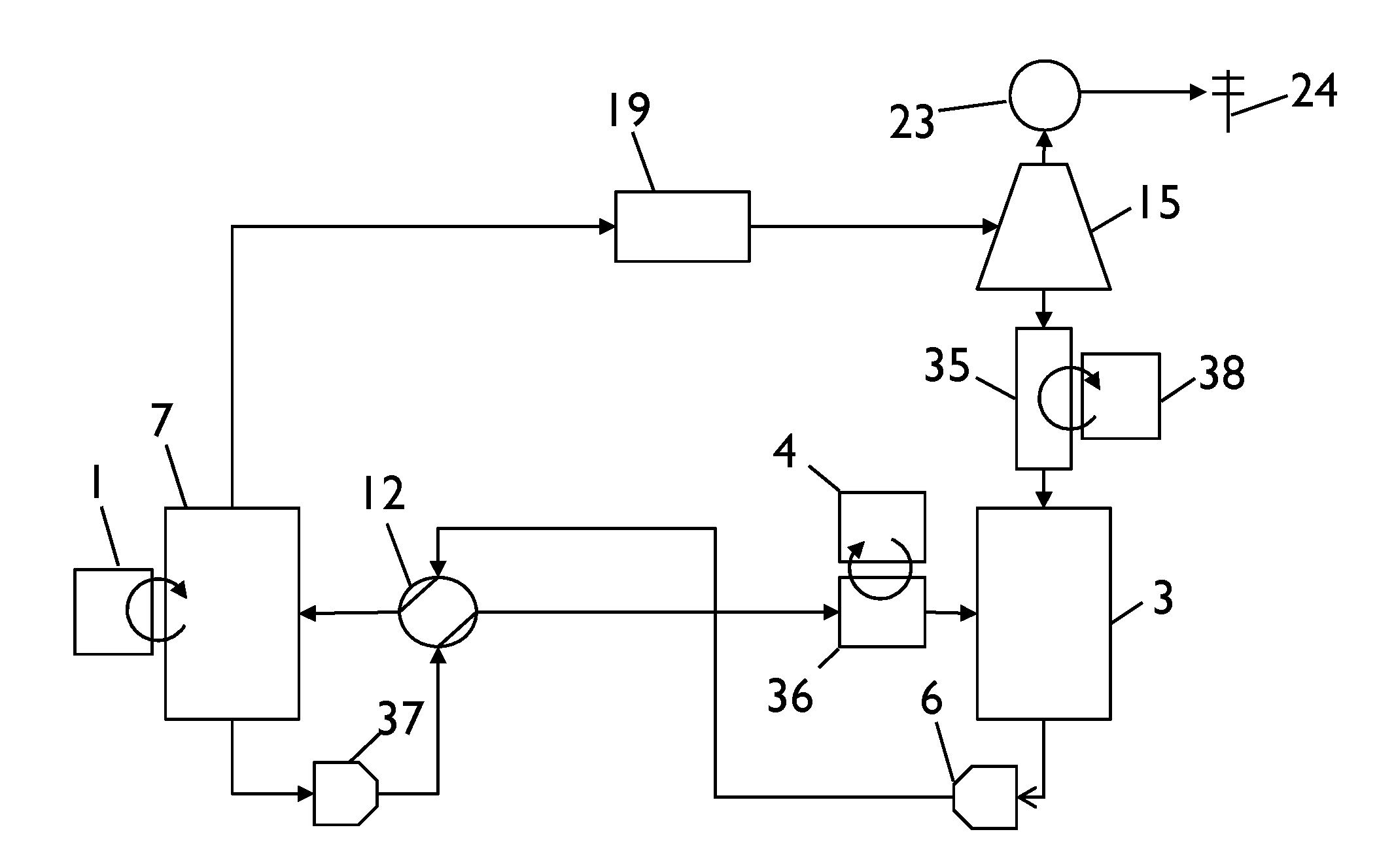
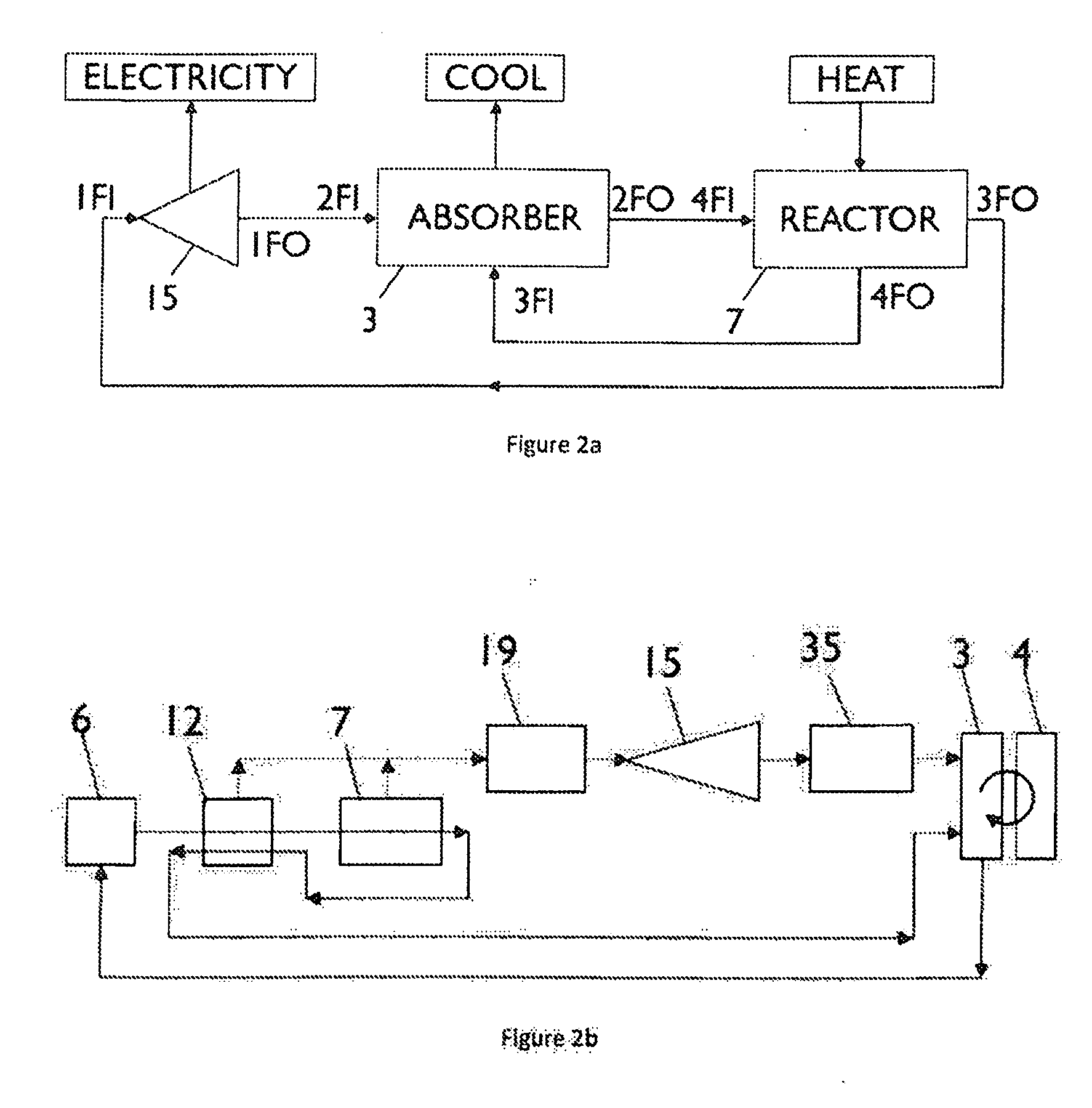
[0043]The Carbon carrier cycle, C3, works in a different way. Heat is used to chemically desorb CO2 from a carrier medium or working fluid. After the CO...


PUM

PropertyMeasurementUnit
temperatureaaaaaaaaaa
pressureaaaaaaaaaa

Abstract

A method for producing electrical energy is disclosed which uses a heat source, such as solar heat, geothermal heat, industrial waste heat or heat from power production processes, providing heat of 150 ° C. or below, further comprising an absorber system in which a working gas, primarily carbon dioxide CO2, is absorbed into an absorbent, typically an amine, further comprising a reactor which receives heat from said heat source and in which the absorbent-CO2 mixture is split into CO2 and absorbent, further comprising an expansion machine, an electricity generator and auxiliary equipment such as pumps, pipes and heat exchangers. The system according to the method allows the cost-efficient production of electrical energy and cooling using low value heat source.

Description

FIELD OF THE INVENTION [0001]The present invention relates to a method, below named Carbon Carrier Cycle, C3, for highly efficient conversion of low temperature heat to electricity and cooling. The invention combines the fields of thermodynamics, chemistry and power generation.BACKGROUND OF THE INVENTION[0002]Current methods of converting low temperature heat below 150° C. to electricity include derivatives of the Rankine cycle such as the Organic Rankine cycle, the Kalina cycle and the Trilateral flash cycle.[0003]Even though the current methods can produce electricity even down to temperatures as low as 60° C., the conversion efficiency is very low and therefore economically unattractive even in applications where the generated heat is available at very low cost.[0004]The main reasons for the low conversion efficiency compared to the ideal Carnot cycle are large energy losses on the entropy reducing cold side of the system and the very small delta T in the gas expansion. This mean...

Claims


Application Information

Patent Timeline
Patent Type & Authority Applications(United States)
IPC IPC(8): F01K15/00C01B32/50
CPCF01K25/065F01K3/00F01K25/103F01K25/06F01K25/10F25B15/02F25B30/06F25B15/00F25B27/007F25B30/04F25B2309/00H02K7/1823
Inventor OSTROM, THOMASKARTHAUSER, JOACHIM
Owner CLIMEON AB
Why Eureka
Try Eureka