
Code symbol reading system employing dynamically-elongated laser scanning beams for improved levels of performance

a laser scanning beam and bar code technology, applied in the direction of instruments, sensing record carriers, sensing by electromagnetic radiation, etc., can solve the problem of reducing the throughput at the retail point of sale (pos), and achieve the effect of improving the snr of reflection intensity signals

Inactive Publication Date: 2013-02-21
METROLOGIC INSTR
View PDF3 Cites 744 Cited by
  • Summary
  • Abstract
  • Description
  • Claims
  • Application Information

AI Technical Summary

Benefits of technology

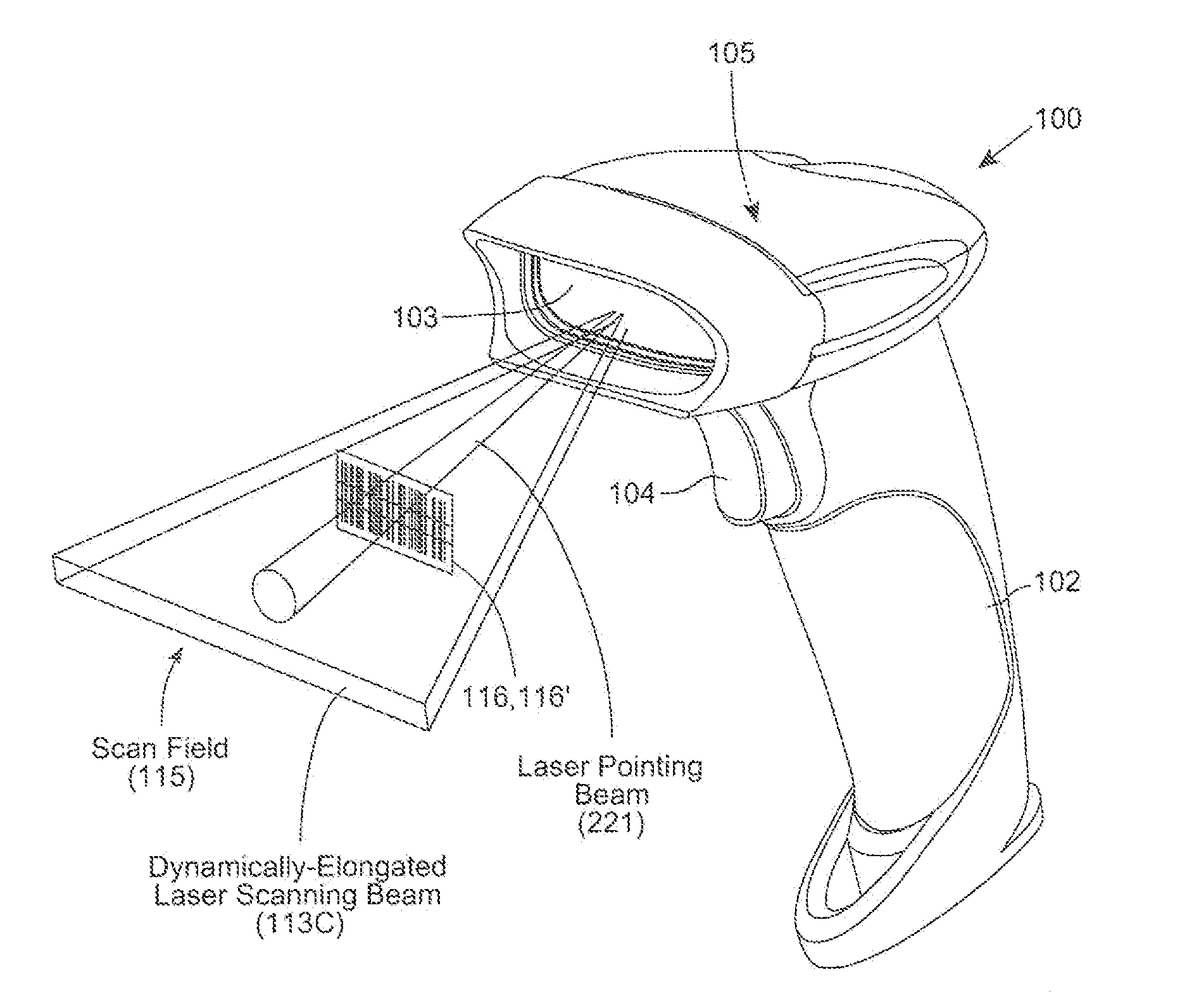
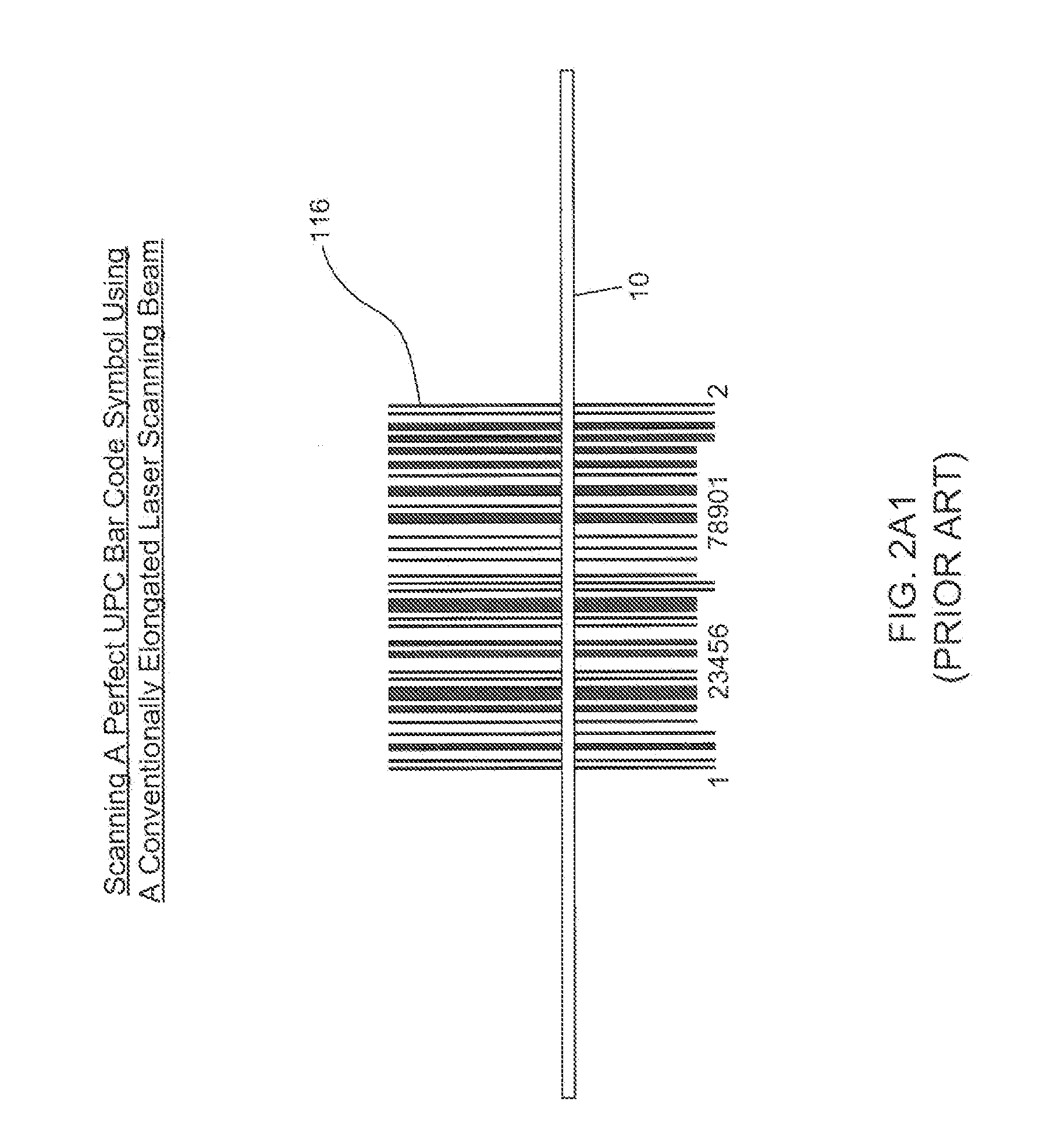
The present patent aims to provide a better way to detect and improve the signal-to-noise ratio (SNR) of bar code symbols during laser scanning. This is done by using laser beams that have dynamically-optimized characteristics, which avoids the shortcomings of previous methods. Additionally, the patent proposes a new method to read poor quality or damaged barcodes by scanning them using a laser beam that has changing beam dimension characteristics in the non-scanning direction. This averages out defects in the bar code symbol during scanning.

Problems solved by technology

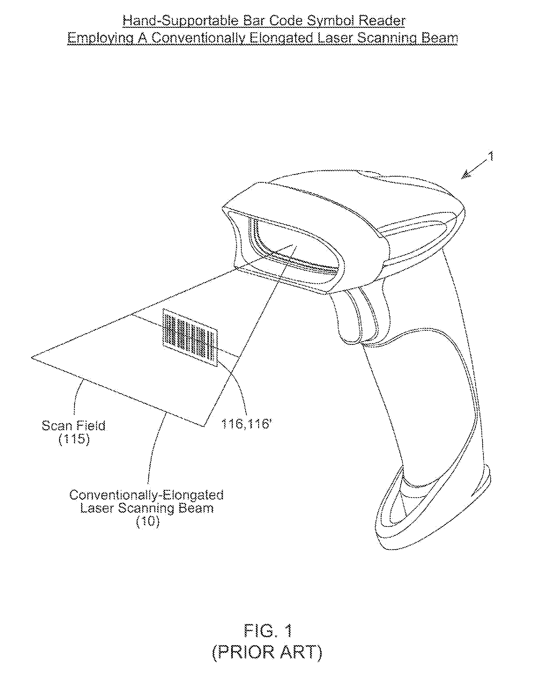
It is well known that poor quality bar codes and damaged bar codes typically results in decreased throughput at the retail point of sale (POS).

Method used


Image

  • Code symbol reading system employing dynamically-elongated laser scanning beams for improved levels of performance
  • Code symbol reading system employing dynamically-elongated laser scanning beams for improved levels of performance
  • Code symbol reading system employing dynamically-elongated laser scanning beams for improved levels of performance

Examples


first embodiment

of the Dynamically-Elongated Laser Beam Production Module

[0089]FIGS. 5A and 5D shows a dynamically-elongated laser beam production module based on the design illustrated in FIG. 4A, for use in the hand-supportable laser scanning bar code symbol reading system of FIG. 3. As shown, the dynamically-elongated laser beam production module 155A comprises: a multi-cavity laser source 112 (e.g. multi-cavity VLD), installed in a yoke assembly 160, having a focusing / collimating lens (i.e. 4.0 [mm] focal length) 161; a lens holder 162 for holding focusing / collimating lens 161, and an aperture stop 163 having a 0.94 [mm] circular diameter, and also holding elongating cylindrical lens (having a radius of curvature of 50 [mm]) 163 along the common optical axis 165 of focusing lens 161, elongating lens 163, and VLD 112, as shown in FIG. 5D.

[0090]A primary object of laser beam production module 155A is to produce a laser beam 113 (114B) having an Elongation Ratio (ER), which dynamically changes bet...

second embodiment

of the Dynamically-Elongated Laser Beam Production Module

[0095]FIG. 6 shows a dynamically-elongated laser beam production module based on the design illustrated in FIG. 4B, comprising: a visible laser diode 112; collimating lens 161 for collimating the laser beam from VLD 112; a variable-focus deformable or liquid crystal (LC) cylindrical lens element 167 for transforming the collimated laser beam into a dynamically-elongated laser beam; and a driver / control circuitry 168, interfacing electro-optical element 167 and system controller 150, for controlling the operation of the variable-focus deformable or liquid crystal (LC) cylindrical lens element 167.

[0096]During operation, the adaptive variable-focus cylindrical lens element 167 is sequentially reconfigured during each laser scanning bar code symbol reading cycle, so that the electro-optical module 155B produces a laser beam having dynamically-changing beam elongation characteristics along the y axis (i.e. non-scanning) direction....


PUM


Abstract

A laser scanning bar code symbol reading system for scanning and reading poor quality and damaged bar code symbols in flexible operating conditions. The system includes a housing having a light transmission window; a dynamically-elongated laser beam production module, including a multi-cavity visible laser diode (VLD), for producing a dynamically-elongated laser beam having (i) a direction of propagation extending along a z reference direction, (ii) a height dimension being indicated by the y reference direction, and (iii) a width dimension being indicated by the x reference direction, where x, y and z directions are orthogonal to each other. Each dynamically-elongated laser beam is characterized by an elongation ratio (ER) that is defined as Y / X where, for any point within the working range of the laser scanning bar code symbol reading system, extending along the z direction, (i) Y indicates the beam height of the dynamically-elongated laser beam measured in the Y reference direction, (ii) X indicates the beam width of the dynamically-elongated laser beam measured in the X reference direction, and (iii) the beam height (Y) and the laser beam width (X) are measured at 1 / e2 intensity clip level. A laser scanning mechanism is provided for scanning the dynamically-elongated laser beam out the light transmission window and across a scanning field defined external to the housing, in which a bar code symbol is present for scanning by the dynamically-elongated laser scanning beam.

Description

BACKGROUND OF DISCLOSURE[0001]1. Field of Disclosure[0002]The present disclosure relates to improvements in bar code symbol reading systems employing laser scanning beams having improved laser beam characteristics which enable the reading of poor quality and / or damaged bar code symbols with enhanced levels of performance.[0003]2. Brief Description of the State of Knowledge in the Art[0004]It is well known that poor quality bar codes and damaged bar codes typically results in decreased throughput at the retail point of sale (POS).[0005]Various techniques have been developed to read poor quality bar codes and damaged bar codes. Such techniques include using: (i) adaptive signal processing gain adjustments and threshold levels (usually performed over a period of several sweeps across the bar code); (ii) reduced signal processing bandwidth to limit high frequency components of scanned data (i.e. limits scanner resolution); (iii) improved decode algorithms to allow for noise in bar code ...

Claims


Application Information

Patent Timeline
IPC IPC(8): G06K7/10
CPCG06K7/10831
Inventor VAN HORN, ERIK
Owner METROLOGIC INSTR
Learn More