
Novel organic compound and organic light emitting element using the same

Active Publication Date: 2013-02-28
CANON KK
View PDF0 Cites 15 Cited by
  • Summary
  • Abstract
  • Description
  • Claims
  • Application Information

AI Technical Summary

Benefits of technology

The present invention provides a novel compound that emits red light and has high hole injection properties. Additionally, an organic red light emitting element that includes this compound and has high efficiency and color purity can also be provided.

Problems solved by technology

However, although the condensed polycyclic compound a-1 emits light in a red spectrum region, the light emitting efficiency and the color purity thereof are not satisfactory.

Method used


Image

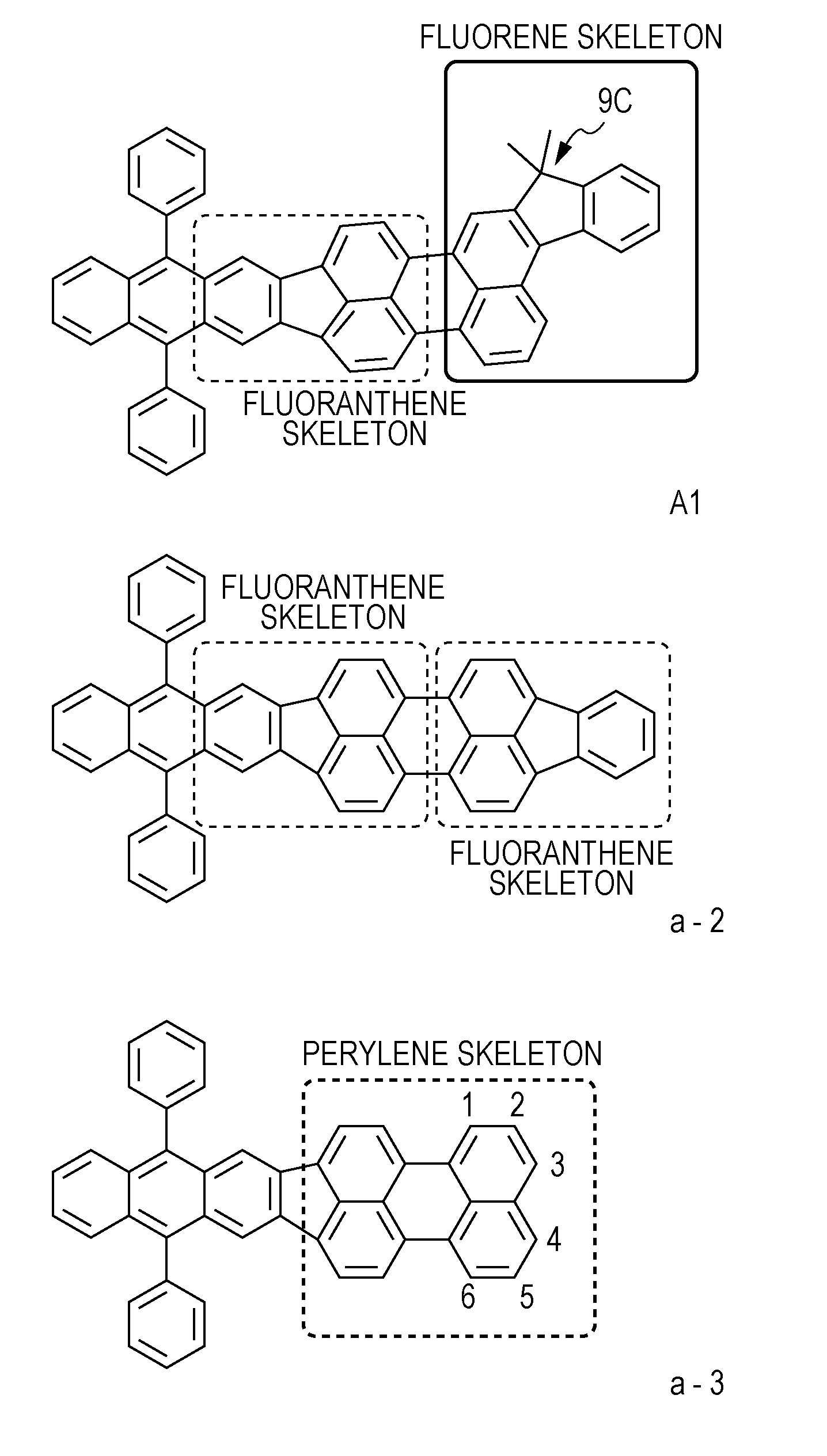
  • Novel organic compound and organic light emitting element using the same
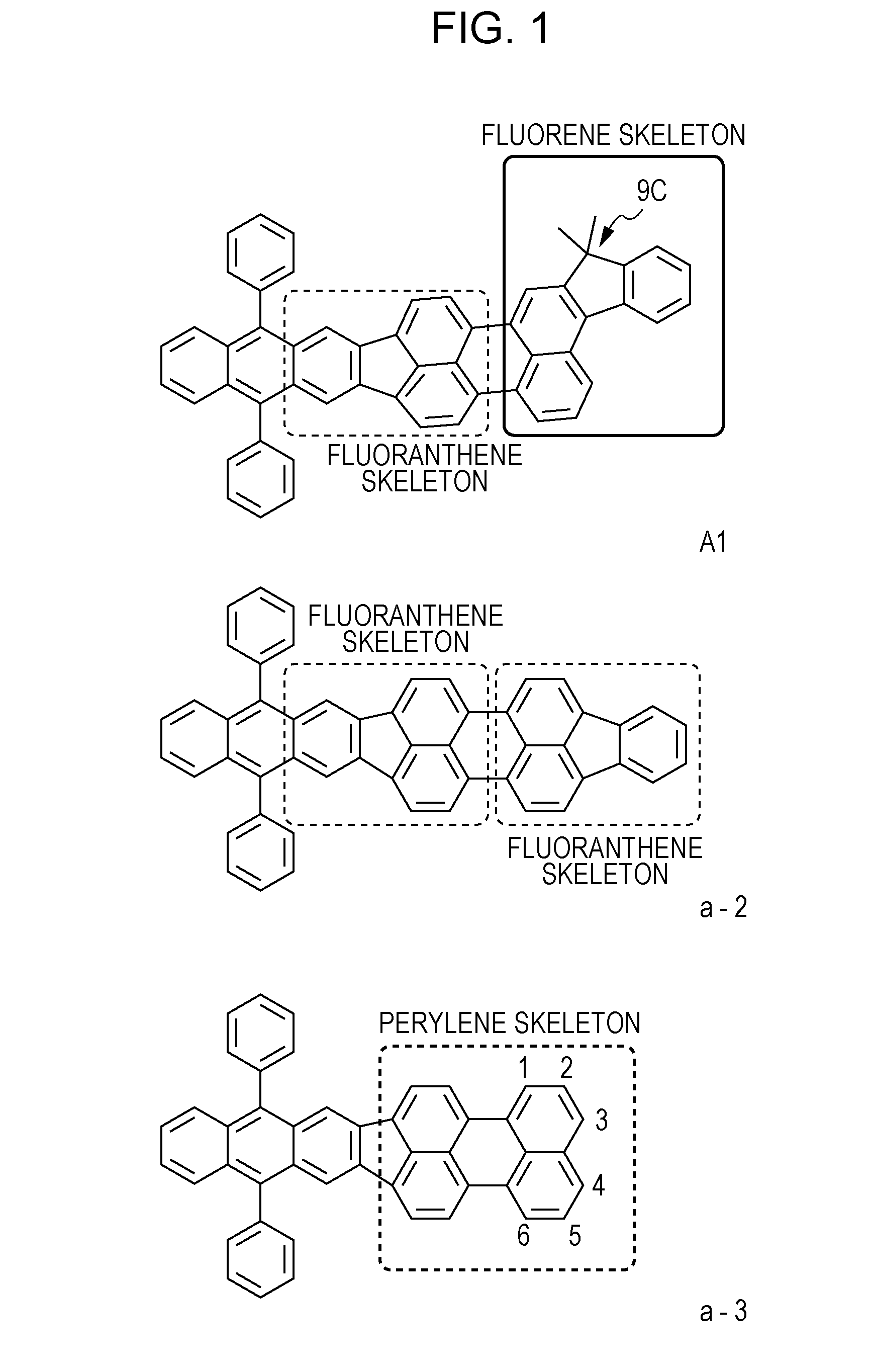
  • Novel organic compound and organic light emitting element using the same
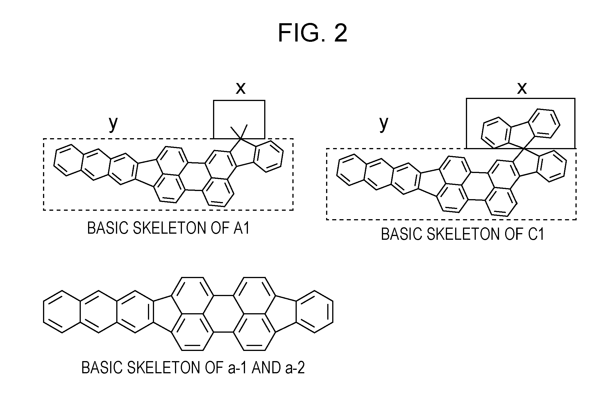
  • Novel organic compound and organic light emitting element using the same

Examples


example 1

Synthesis of Example Compound (C1)

[0117]After a toluene solvent (42 ml) was deaerated, 0.28 g (1.25 mmol) of palladium acetate(II) and 0.62 g (2.50 mmol) of s-phos were added and were then stirred for 10 minutes at room temperature. Subsequently, after 4.74 g (12.5 mmol) of the compound (F2), 3.19 g (2.50 mmol) of potassium phosphate, and distilled water (1 ml) were added, 5.0 g (12.5 mmol) of the compound (F1) was finally added, and stirring was performed at 95° C. for 3 hours. After cooling, methanol was added, and filtration was then performed. After chlorobenzene (500 ml) was added to this residue and was heated to 100° C., this solution in this state was then processed by a silica gel column chromatography (moving phase; toluene) followed by condensation. After the condensed product was dispersed and washed with acetone, filtration was performed followed by drying, so that 5.96 g of the orange solid (F3) was obtained (yield: 77%).

[0118]After a DMF solvent (180 ml) was deaerated...

example 2

Synthesis of Example Compound (A1)

[0125]The following synthetic reaction was performed as in the case of Example 1 except that the compound (F8) was changed to the following compound (F12), so that the following compound (F14) (example compound (A1)) was synthesized.

[0126]After a toluene solvent (18 ml) was deaerated, 39 mg (0.043 mmol) of Pd2(dba)3(0) and 61 mg (0.13 mmol) of x-phos were added and were then stirred for 10 minutes at room temperature. Subsequently, after 600 mg (0.85 mmol) of the compound (F7), 192 mg (0.89 mmol) of the compound (F12), 540 mg (2.6 mmol) of potassium phosphate, and distilled water (0.5 ml) were added, stirring was performed at 120° C. for 2 hours. After cooling, extraction was performed with toluene, and drying was then performed with sodium sulfate. After condensation was performed, the product thus obtained was then processed by a silica gel column chromatography (moving phase; toluene), and condensation and drying were then performed.

[0127]After c...

example 3

Synthesis of Example Compound (B1)

[0130]Except that the compound (F12) was changed to the following compound (F15), the example compound (B1) was synthesized in a manner similar to that of Examples 1 and 2.

[0131]By a mass spectrometry, M+ of the example compound (B1) was confirmed to be 770.

[0132]In addition, as in the case of Example 1, when the emission spectrum of the example compound (B1) in a toluene diluted solution was measured at room temperature, the maximum emission wavelength was 603 nm.


PUM

PropertyMeasurementUnit
Electric potential / voltageaaaaaaaaaa
Lightaaaaaaaaaa

Abstract

An organic compound represented by the following general formula [1] is provided. In the general formula [1], R1 to R3 are each independently selected from the group consisting of a hydrogen atom, a fluorine group, an alkyl group having 1 to 4 carbon atoms, and an aryl group, the aryl group is a phenyl group, a biphenyl group, or a terphenyl group, the aryl group may further include an alkyl group having 1 to 4 carbon atoms and / or a fluorine group as a substituent, and R4 to R17 are each independently selected from the group consisting of a hydrogen atom, an alkyl group having 1 to 4 carbon atoms, and a fluorine group.

Description

BACKGROUND OF THE INVENTION[0001]1. Field of the Invention[0002]The present invention relates to a novel organic compound and an organic light emitting element including the same.[0003]2. Description of the Related Art[0004]An organic light emitting element is an element including a pair of electrodes and an organic compound layer arranged therebetween. When an electron and a hole are injected from the pair of electrodes, an exciton is generated in a light emitting organic compound of the organic compound layer, and light is emitted when the exciton returns to the ground state.[0005]The organic light emitting element is also called an organic electroluminescent element or an organic EL element.[0006]The recent advances in the organic light emitting element are remarkable, and a high-speed response, thin, and lightweight light emitting device which can be driven at a low voltage and which has various light emitting wavelengths can be formed.[0007]Heretofore, creation of novel red lig...

Claims


Application Information

Patent Timeline
IPC IPC(8): C07C13/72H05B37/00H05B33/14
CPCY10S428/917C09K11/06H01L51/5012C09K2211/1011H01L51/0056C07C2103/94H01L51/0072H01L2251/308C07C13/62C07C13/72C07C2103/90H01L51/006C07C2603/90C07C2603/94H10K85/624H10K85/633H10K85/6572H10K50/11H10K2102/103
Inventor NISHIDE, YOSUKEWATANABE, TAIKIKOSUGE, TETSUYAYAMADA, NAOKISAITOH, AKIHITO
Owner CANON KK
Learn More