
Method and apparatus for climatic conditioning of space within a building structure

a climatic conditioning and building structure technology, applied in the direction of domestic cooling apparatus, lighting and heating apparatus, etc., can solve the problems of limited thermal energy storage and release, climatic control systems have not been successful at providing thermal comfort in building structures, and evaporative cooling and indirect evaporative cooling systems have only limited success with respect to compressed gas cooling systems, etc., to achieve the effect of increasing the thermal mass of said building construction articles, extending the period of time, and low energy consumption

Inactive Publication Date: 2013-03-07
EVERETT STEVE EUGENE
View PDF12 Cites 14 Cited by
  • Summary
  • Abstract
  • Description
  • Claims
  • Application Information

AI Technical Summary

Benefits of technology

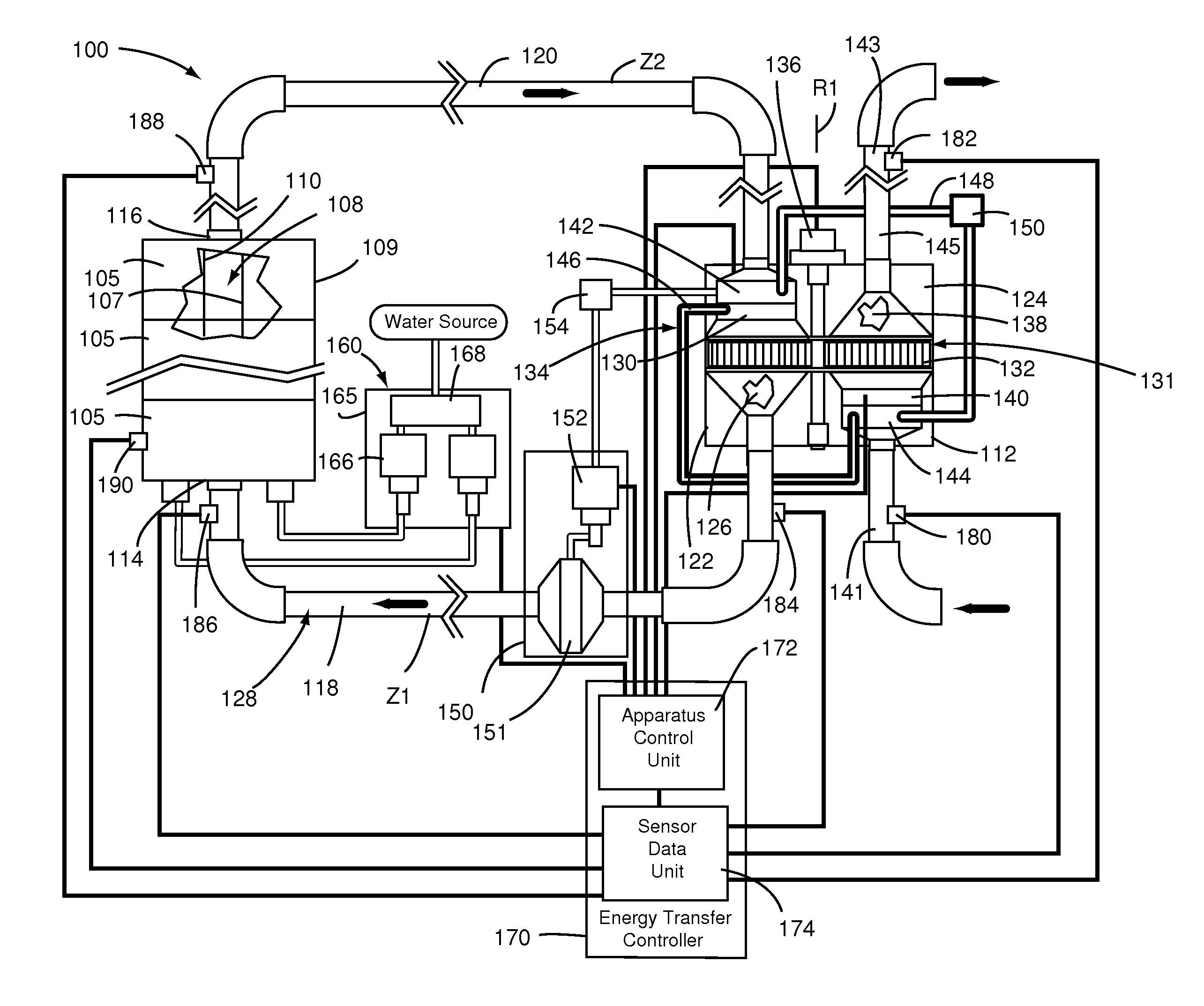
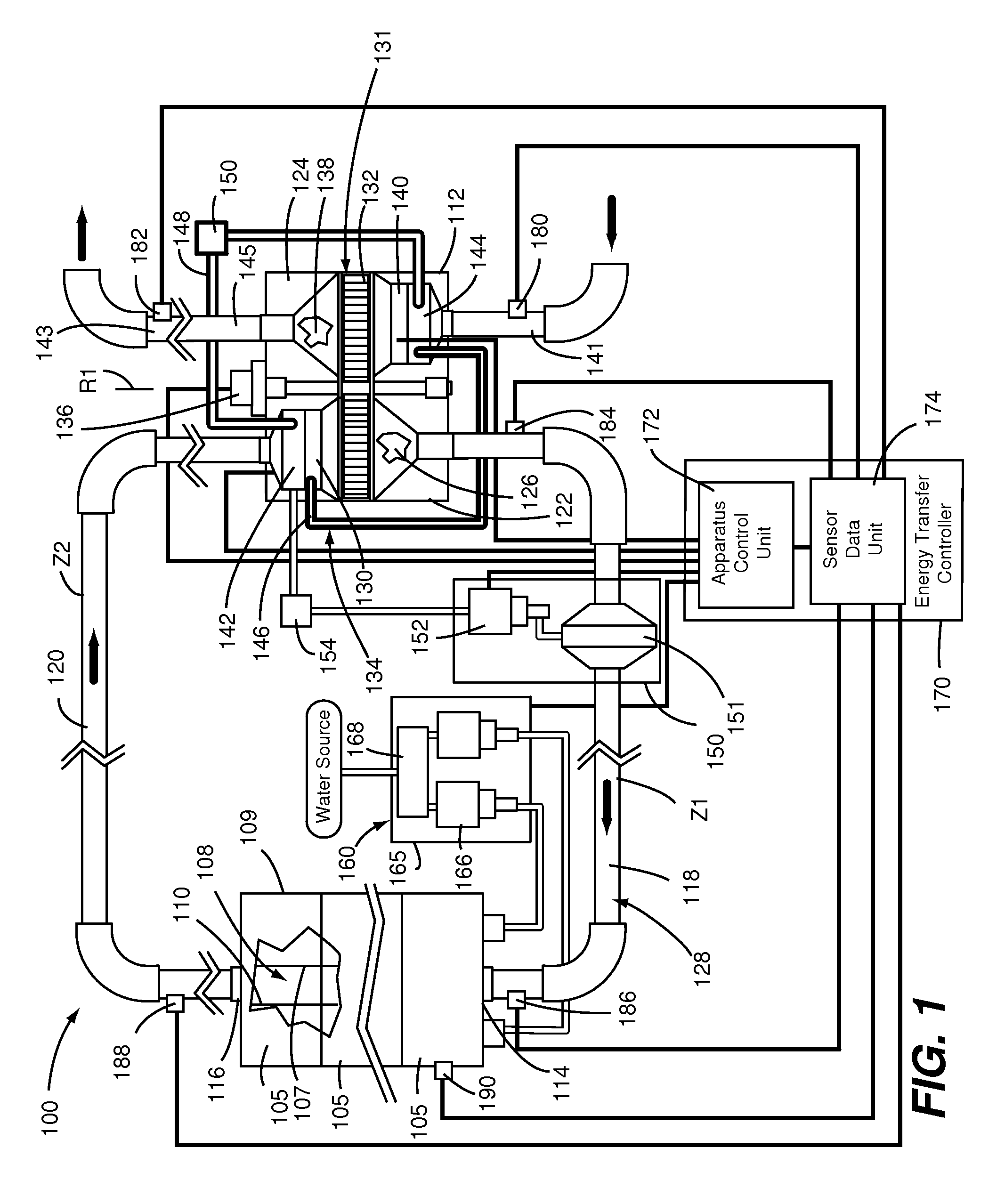
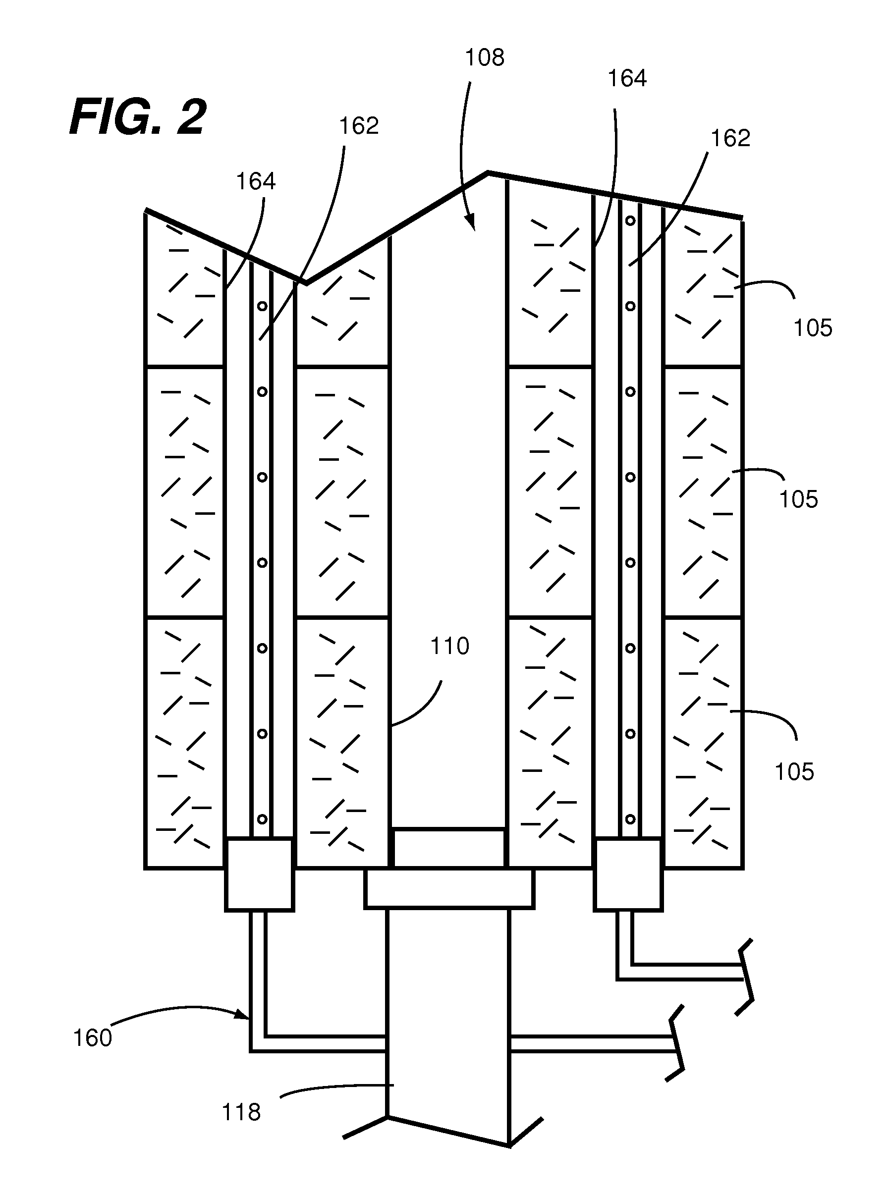
The present invention provides a thermal conditioning system for buildings that can efficiently provide low thermal energy consumption and effective working in multiple climate zones. The system uses multiple water vapor phase change cycles within a heat sink mass to transfer heat and create a comfortable interior climate. The system includes hygroscopic heat sink mass building construction articles that have high vapor permeability and elevated hygroscopic properties, which are important for promoting the efficient diffusion of water vapor, condensation of water vapor, transfer of liquid water through capillary suction, and the evaporation of water into / out of the building construction articles. The system also includes an airflow imparting apparatus, humidifying apparatus, dehumidifying apparatus, heat transfer controller, and sensible air heating and cooling devices. The efficiency of the system depends upon the predetermined properties of the building construction articles and the capacity of the conditioning system to provide a continuous selectively controlled volume of air with pronounced vapor pressure differentials between the building construction articles and the circulating air streams.

Problems solved by technology

While fusion type phase change materials change phase from a solid to a liquid, they are limited in the amount of thermal energy they can store and release.
However, in climate zones that are hot and humid, evaporative cooling and indirect evaporative cooling systems have had only limited success with respect to compressed gas cooling systems.
Desiccant air drying in combination with evaporative cooling have also been tried with some success, but require large systems to condition the total cubic area within a living space of a building structure.
In this regard, such known climatic control systems have not been successful at providing thermal comfort in a building structure in hot and humid climates in a manner that utilizes low energy consumption.
Transferring thermal energy through a water circulating system within a heat sink mass of a building structure for heating and cooling is very efficient, but is not very cost effective in that the cost of the additional materials such a piping, pumps and heat exchangers for cooling and heating fluids increase costs of heating and cooling the building structure.
While this climatic conditioning of a living space within a building structure made using adobe heat sink masses using the natural method of heating and cooling a building structure works very well, it has limitations based on the limited natural cycles of cool, humid evenings and warm dry days.
The limiting factor in the effectiveness of this climatic conditioning is the limited number of thermal conditioning cycles transpiring in a given time frame (e.g., typically one cycle per day).

Method used


Image

  • Method and apparatus for climatic conditioning of space within a building structure
  • Method and apparatus for climatic conditioning of space within a building structure
  • Method and apparatus for climatic conditioning of space within a building structure

Examples


Embodiment Construction

[0019]Embodiments of the present invention provide a means for climatically conditioning the hygroscopic heat sink mass of the building construction articles and the cavities within the heat sink mass of the building structure to a moist condition and then to very dry climatic condition. A primary object of such embodiments is the climatic conditioning (sensible and latent) of the permanent heat sink mass of the building structure (e.g., building construction articles thereof) and more specifically a method and apparatus for the conditioning of the hygroscopic permanent heat sink mass. The heat sink mass comprises building construction articles having hygroscopic properties and a heat sink mass size to support thermal energy for extended periods of time and thereby extending the periods of time between activation of the cycled conditioned air streams. Furthermore the periods of time between activation of cycled conditioned air streams can be extended by the incorporation of fusion t...


PUM


Abstract

A method and apparatus are configured for providing thermal comfort (i.e., climatic conditioning) within an interior space of a building structure in multiple climate zones including hot and humid climates using very low energy consumption. Multiple water vapor phase change cycles are provided within a period of time where only a single such water vapor phase change cycle would typically take place under naturally occurring ambient conditions. These multiple water vapor phase change cycles are generated through artificially creating conditions within a hygroscopic heat sink mass for promoting water vapor phase change cycle. Advantageously, in combination with such artificially promoted water vapor phase change cycles, embodiments of the present invention provide hygroscopic properties and heat sink masses made from materials that can adsorb and retain thermal energy and that exhibit water vapor sorption / desorption attributes commonly associated with compositions referred to as desiccants.

Description

CROSS REFERENCE TO RELATED APPLICATIONS[0001]This patent application claims priority from the following co-pending U.S. Provisional Patent Applications all having a common applicant herewith and being incorporated herein in their entirety by reference: Ser. No. 61 / 575,959, filed Sep. 1, 2011, entitled “Method And Apparatus For Climatic Conditioning Of A Building Structure”; Ser. No. 61 / 628,048, filed Oct. 24, 2011, entitled “Method And Apparatus For Climatic Conditioning Of A Heat Sink Mass Of A Building Structure”; and Ser. No. 61 / 631,218, filed Dec. 30, 2011, entitled “Method And Apparatus For Climatic Conditioning Of A Building Structure”.FIELD OF THE DISCLOSURE[0002]The disclosures made herein relate generally to approaches for providing climatic conditioning of a building structure and, more particularly, to utilizing a controlled moisture differential in combination with building structure materials having desiccant-like properties to provide for climatic conditioning of a spa...

Claims


Application Information

Patent Timeline
Patent Type & Authority Applications(United States)
IPC IPC(8): F25D17/04F25D31/00
CPCF28D20/003Y02E60/147F24F5/0021F24F3/14Y02B10/20Y02E60/14
Inventor EVERETT, STEVE EUGENE
Owner EVERETT STEVE EUGENE
Learn More