Dual-Mode Piezocomposite Ultrasonic Transducer

a piezocomposite, ultrasonic transducer technology, applied in the field of ultrasonic transducers, can solve the problems of loss of acoustic efficiency, mechanical steering, and increased risk of radiotherapy and chemotherapy for tumor cells, and achieve the effect of improving the ultrasonic transducer and effectively operating

a piezocomposite, ultrasonic transducer technology, applied in the field of ultrasonic transducers, can solve the problems of loss of acoustic efficiency, mechanical steering, and increased risk of radiotherapy and chemotherapy for tumor cells, and achieve the effect of improving the ultrasonic transducer and effectively operating

US20130060140A1Active Publication Date: 2013-03-07MISONIX INC

Image

  • Dual-Mode Piezocomposite Ultrasonic Transducer
  • Dual-Mode Piezocomposite Ultrasonic Transducer
  • Dual-Mode Piezocomposite Ultrasonic Transducer

Examples


Embodiment Construction

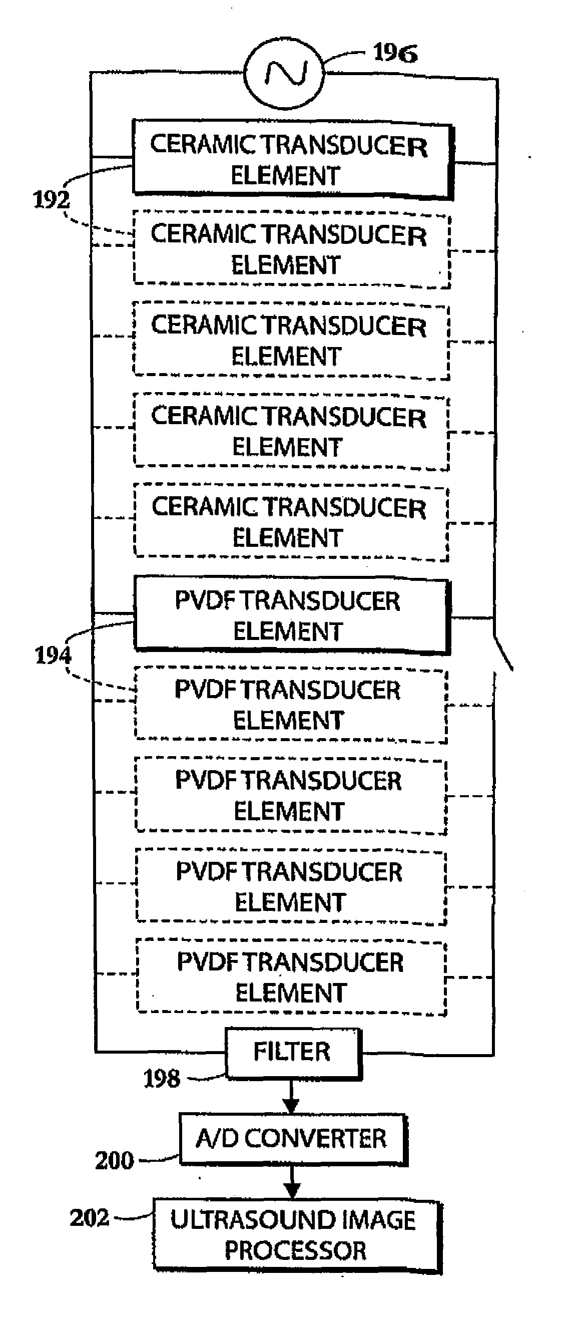
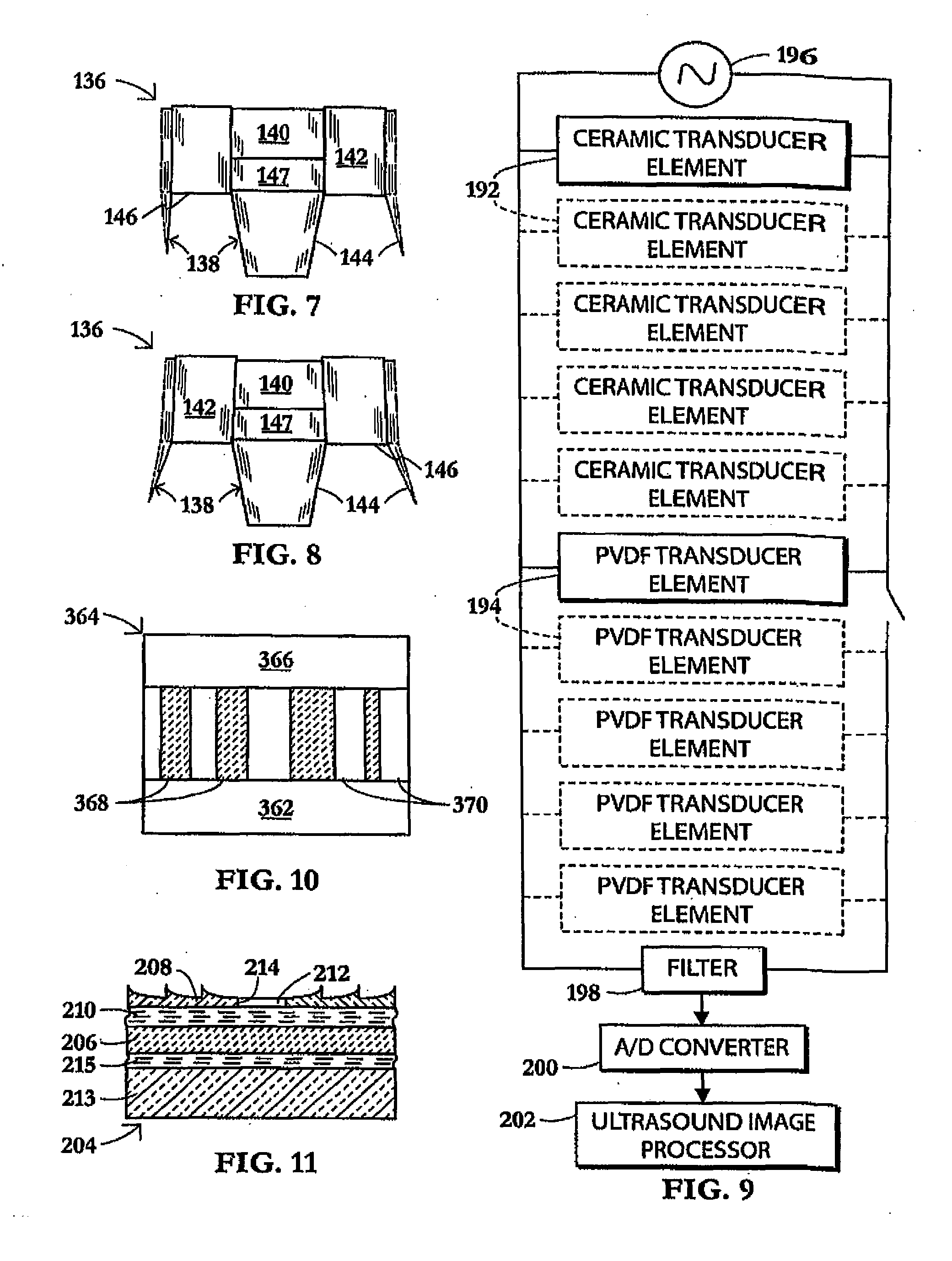
[0062]The present invention stems in part from an appreciation of the properties of polyvinylidene fluoride (PVDF), which is a semi-crystalline, thermoplastic fluoroplastic. It has received a considerable research attention in past decades after its piezoelectric and pyroelectric properties were discovered and it found a subsequent application as an electret and piezoelectric transducer. With its low acoustic impedance of 3.5 MRyals and high voltage constant PVDF makes an ideal ultrasound receiver and shows definite advantages over ceramic counterparts (Gallentree, 1983, Review of Transducer Applications of Polyvinylidene Fluoride, Piezoelectricity, Key Paper in Physics, 189-194). As a transmitter of acoustic power, the PVDF transducer is quite poor, its dielectric losses are quite high, but its enhanced sensitivity on reception provides a send-receive factor comparable to that of ceramic. Table below summarized common applications and lists relevant piezoelectric properties for typ...


PUM


Abstract

A compact, high power, dual mode, emitting and receiving ultrasound transducer and method for applying ultrasonic energy within a living subject and for monitoring the effects it induces in tissue comprises a set of piezoelectric polymeric transducer elements and a set of piezoelectric ceramic elements, bonded together. The polymeric transducer elements have electrodes enabling their use for low power diagnostic imaging interrogation of the tissue and the ceramic transducer elements have electrodes enabling their use for high power therapy applications.

Description

FIELD OF INVENTION[0001]The present invention relates to ultrasonic transducers.BACKGROUND OF THE INVENTION[0002]This invention is directed in principal part to an ultrasonic transducer device. More particularly, this invention is directed to a dual mode ultrasonic transducer device, one that can be used for both diagnostic investigations and therapy.[0003]Ultrasound is widely used in modern medicine for diagnostics and treatment in such fields as obstetrics, cardiology, endocrinology, gastroenterology, neurology, ophthalmology, urology, osteoporosis, and clinical diagnostics. A wide range of clinical trials are being conducted for breast tumor ablation, urine fibroids ablation, benign prostatic hyperplasia ablation, fibrillation, cardiac, bleeding control, and brain disorder treatments (Clement, 2004, Perspectives in clinical uses of high intensity focused ultrasound, Ultrasonics, 42, 1087-1093).[0004]Ultrasound diagnostics uses low-power ultrasonic scanners for investigation and v...

Claims


Application Information

Patent Timeline
07 Mar 2013
Publication
US20130060140A1
IPC
A61B8/13; A61N7/00
CPC
A61B2018/0016; A61B2018/00577; A61B2019/5276; A61N7/00; A61B8/485; A61N2007/0078; B06B1/0629; A61B8/4483
Inventors
SINELNIKOV, YEGOR