

System and method for blood vessel stenosis visualization and navigation
a technology for blood vessels and navigation systems, applied in the field of diagnostic imaging, can solve the problems of affecting patient throughput, requiring a great deal of time on the part of medical personnel, and time-consuming process, and affecting patient throughpu
- Summary
- Abstract
- Description
- Claims
- Application Information
AI Technical Summary
Benefits of technology
Problems solved by technology
Method used
Image

Examples
Embodiment Construction
[0018]The operating environment of the invention is described with respect to a sixty-four-slice computed tomography (CT) system. However, it will be appreciated by those skilled in the art that the invention is equally applicable for use with single-slice or other multi-slice configurations. Moreover, the invention will be described with respect to the detection and conversion of x-rays. However, one skilled in the art will further appreciate that the invention is equally applicable for the detection and conversion of other high frequency electromagnetic energy. An implementation is employable with a “third generation” CT scanner and / or other CT systems.
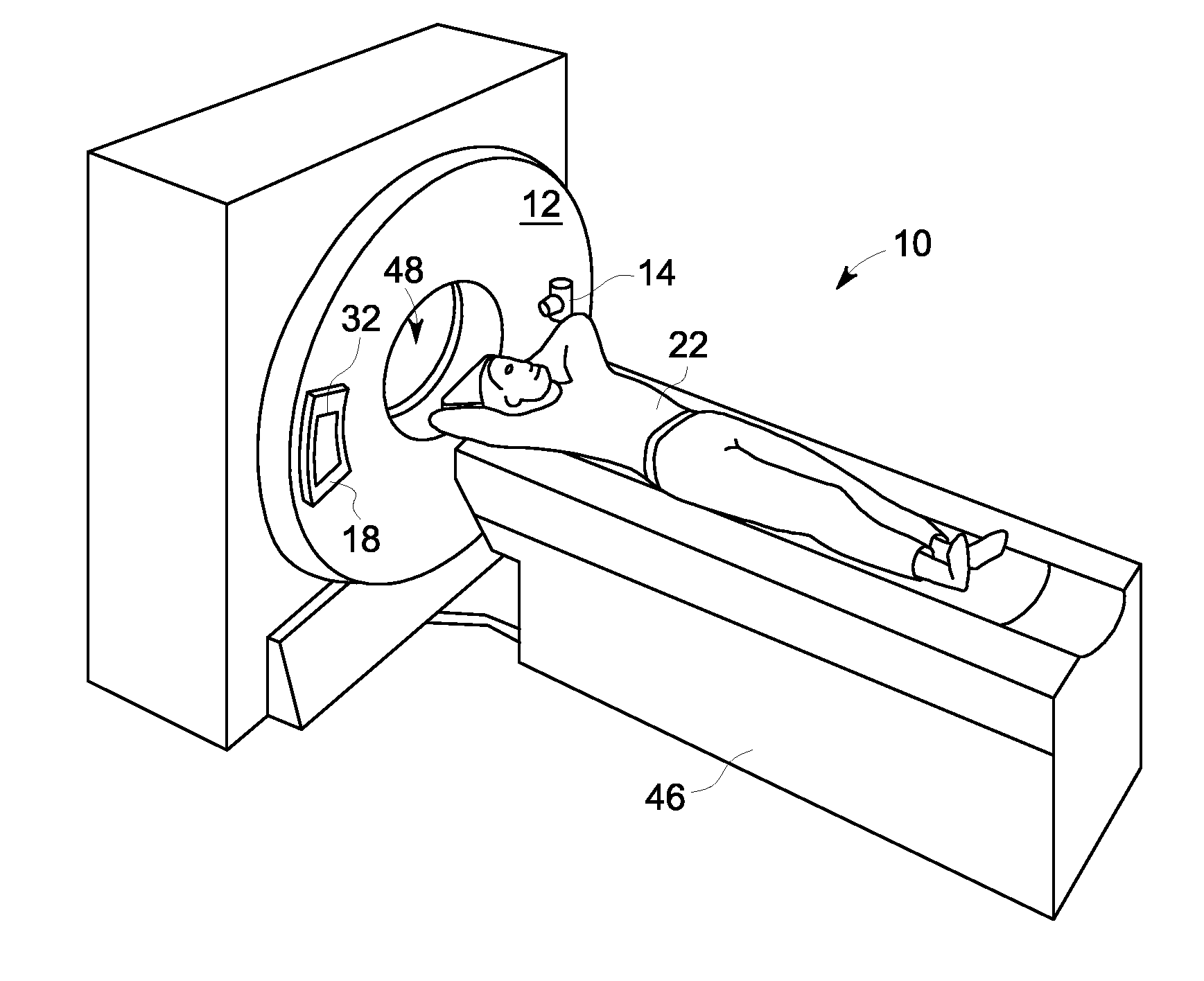
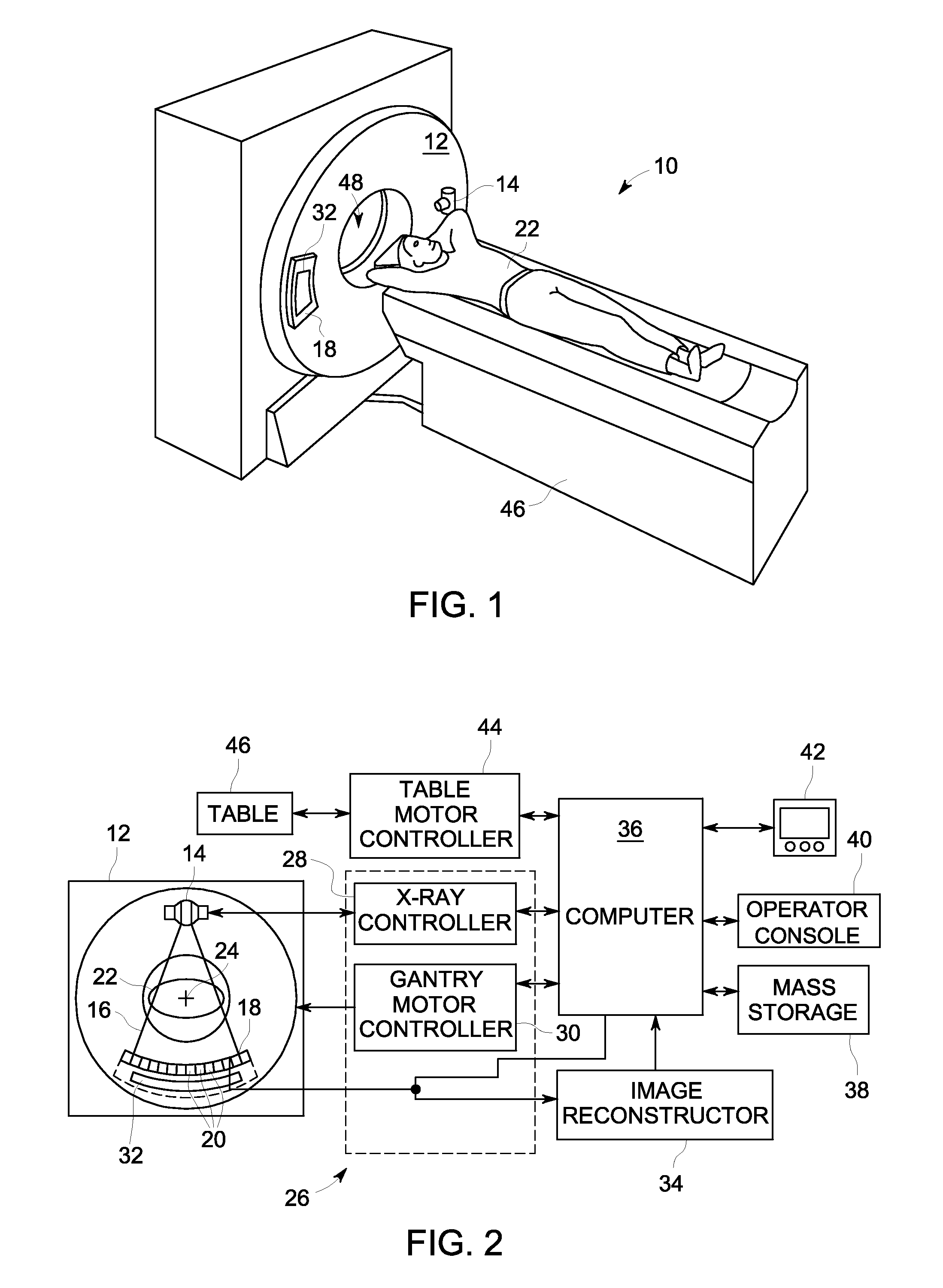
[0019]Referring to FIG. 1, a computed tomography (CT) imaging system 10 is shown as including a gantry 12 representative of a “third generation” CT scanner. According to an exemplary embodiment of the invention, CT system 10 is provided as a Gemstone Spectral Imaging (GSI) dual energy CT system from GE Healthcare. Gantry 12 has an x...
PUM
 Abstract
Description
Claims
Application Information