Ceramic encapsulations for nuclear materials and systems and methods of production and use

a technology of nuclear materials and encapsulations, applied in the direction of instruments, distance measurement, greenhouse gas reduction, etc., can solve the problems of large residual heat generation, high cost, and high cost of both materials, and achieve the effect of improving heat transfer

Inactive Publication Date: 2013-03-28
TORXX GROUP
View PDF0 Cites 37 Cited by
  • Summary
  • Abstract
  • Description
  • Claims
  • Application Information

AI Technical Summary

Benefits of technology

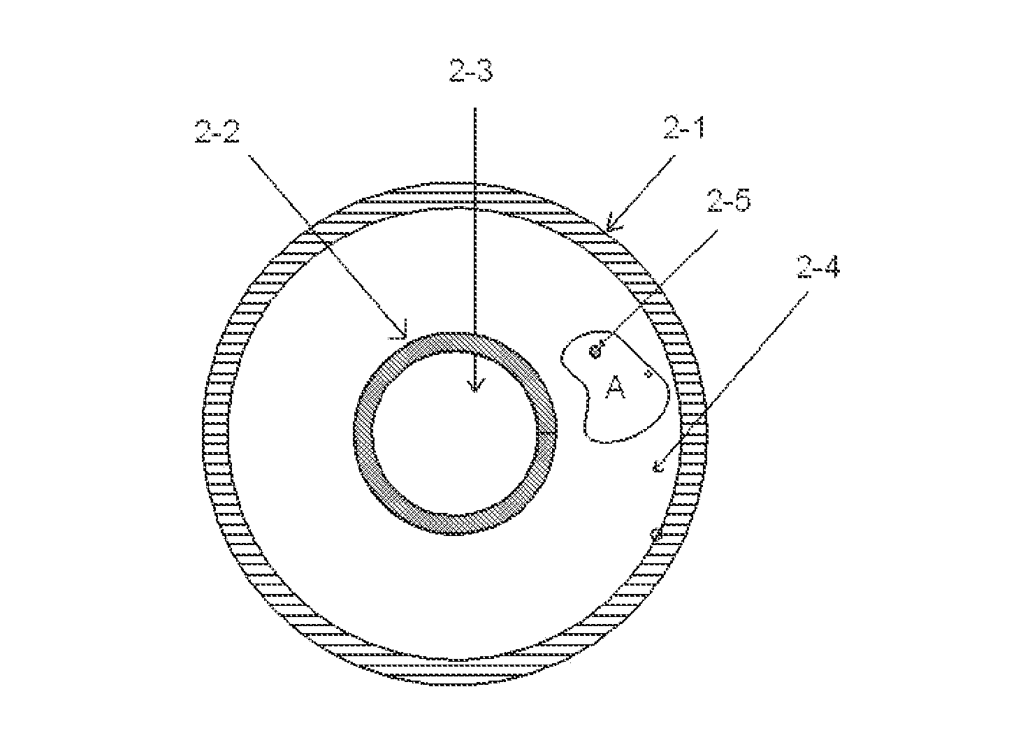
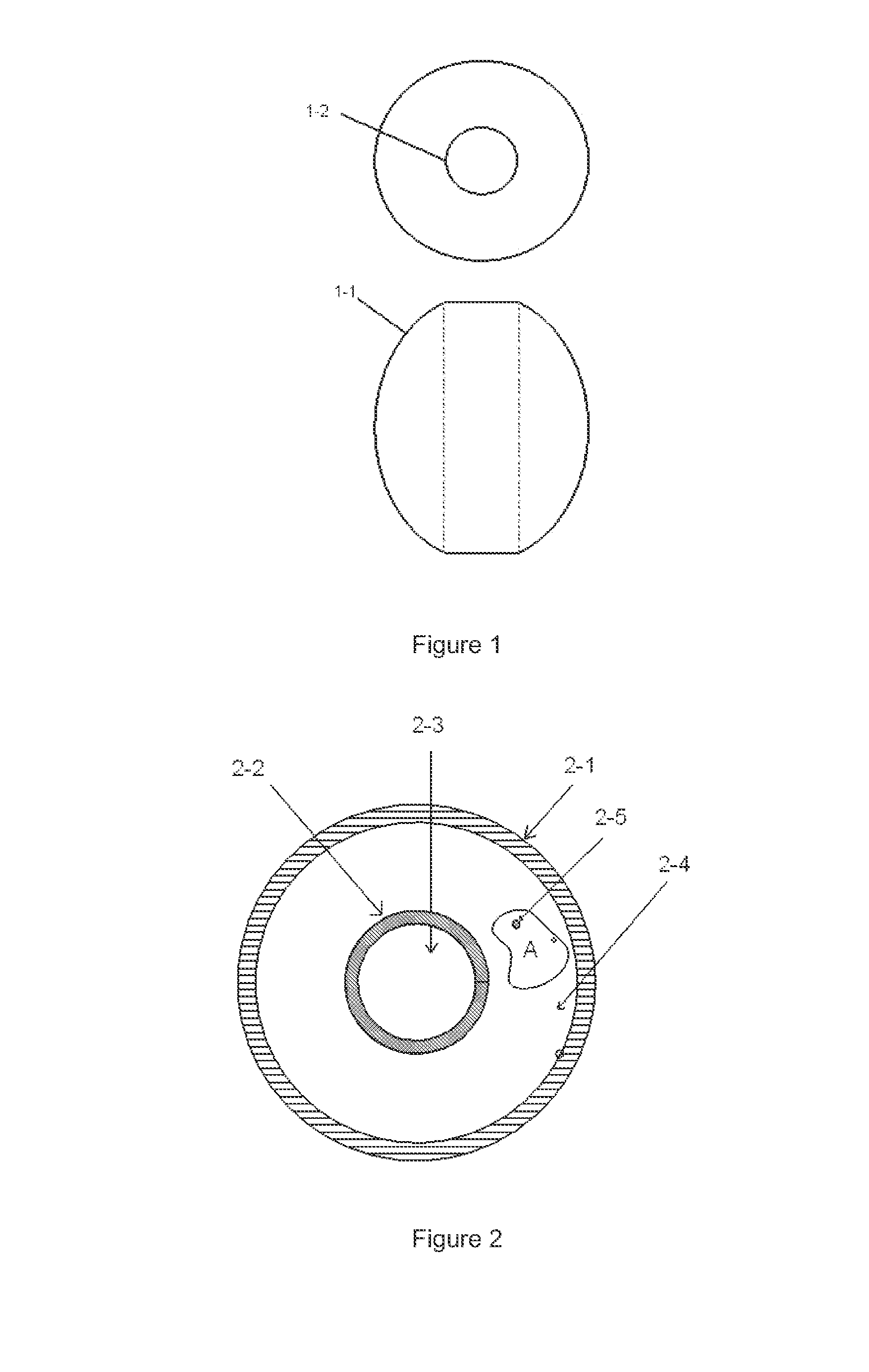
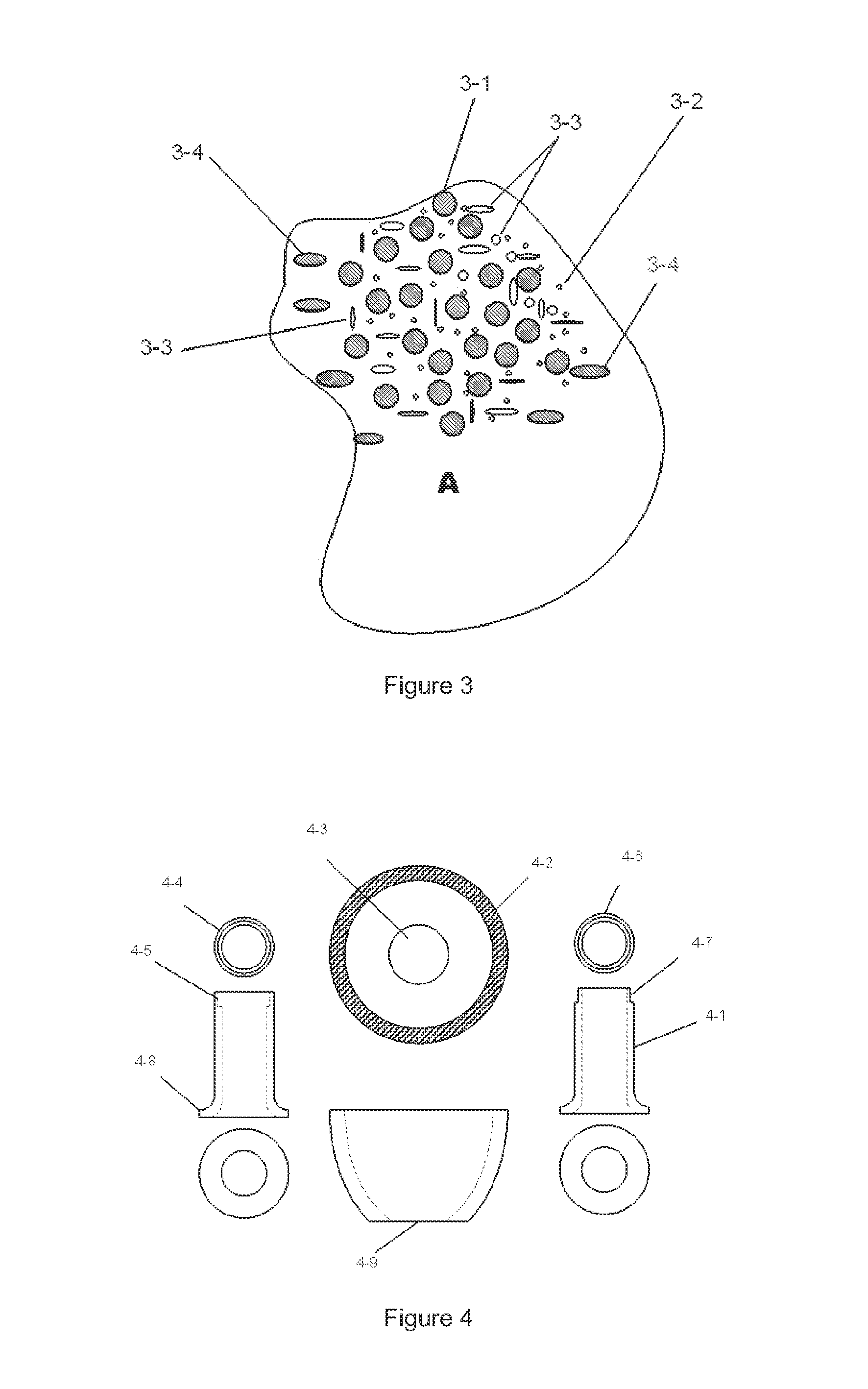
[0005]The present invention describes a novel ceramic composite based nuclear fuel containment structure. The structure and materials are non-reactive, strong at high temperatures, are radiation resistant, and do not require water-cooling to function safely. The invention embodies a novel containment structure in the form of an oval ceramic “bead” structure with an annulus through the center. The open center annulus permits dramatically improved heat transfer compared to standard “pebbles” used in pebble bed reactors. Further embodiments include the use of ceramic forming polymers to replace graphite as the primary structure of the bead. The ceramic formed from the polymers is silicon carbide (SiC) which is stable in water, steam, and very hig...

Problems solved by technology

Since conventional reactors rely on massive amounts of water to keep the zirconium clad fuel rods from melting, any significantly long interruption in the coolant flow can result in the core very rapidly heating enough to either produce high pressure steam in a BWR or high pressure hydrogen in a PWR.
Even after a full SCRAM—full insertion of the control rods into the...

Method used


Image

  • Ceramic encapsulations for nuclear materials and systems and methods of production and use
  • Ceramic encapsulations for nuclear materials and systems and methods of production and use
  • Ceramic encapsulations for nuclear materials and systems and methods of production and use

Examples


example

One Ceramic Composite Fuel Bead Manufacturing Route

[0023]One possible route to manufacturing of the fuel beads would be to make outer and inner gas-impervious component separately away from the radioactive fuel. An example bead fabrication route is provided:

[0024]Outer shell and Inner Tube Fabrication:

[0025]The inner tube would be molded in two separate tubes of lengths equivalent to roughly ⅔ of the desired inner tube length that would be bonded together during the bead assembly. Each tube would have a flared end to assist in bonding to the outer shell, with the other ends molded / machined to provide a joint that could be assembled and sealed / bonded during bead assembly. The tubes would be made by sliding a braided tube of SiC or other ceramic fiber onto a mandrel of a diameter equivalent to the desired inner tube diameter. The ceramic fiber tube would be composed of at least two and no more than 6 layers of braided ceramic tubing that were coated with a slurry of ceramic forming po...


PUM

PropertyMeasurementUnit
Temperatureaaaaaaaaaa
Electrical resistanceaaaaaaaaaa
Shapeaaaaaaaaaa

Abstract

A novel containment system for encapsulating nuclear fuel particles is disclosed. The containment system has a gas-impervious ceramic composite hollow shell having a spheroidal or ovoidal shape. The shell has a pair of longitudinally aligned round openings that are sealed with a gas-impervious ceramic composite tube to define a cavity between the shell inner surface and the tube outer surface. A ceramic composite matrix containing the nuclear fuel particles is enclosed within the cavity. The ceramic composite matrix has a controlled porosity, and can contain moderators or neutron absorbing material. The tube and shell are composed of a ceramic matrix composite material composed of ceramic reinforcement material that is bound together by a polymer-derived ceramic material.

Description

CROSS-REFERENCE TO RELATED APPLICATION[0001]This application claims the benefit of U.S. Provisional Application No. 61 / 468,490, filed Mar. 28, 2011, the entirety of which are hereby incorporated by reference.BACKGROUND[0002]The Primary Concern with conventional PWR and BWR reactors systems has always been containing the steam and hydrogen pressure generated in a loss of coolant accident (LOCA) . . . we all remember 3-Mile Island. Since conventional reactors rely on massive amounts of water to keep the zirconium clad fuel rods from melting, any significantly long interruption in the coolant flow can result in the core very rapidly heating enough to either produce high pressure steam in a BWR or high pressure hydrogen in a PWR. Even after a full SCRAM—full insertion of the control rods into the reactor to try to shut down the fission reaction (or at least slow it down), large amounts of residual heat is generated.[0003]Events in Japan in 2011 highlight the clear and present danger of ...

Claims


Application Information

Patent Timeline
IPC IPC(8): G21C3/07
CPCG21C3/07Y02E30/38G21C21/02G21C3/62Y02E30/30
Inventor SHERWOOD, WALTER J.COYLE, DOUGLAS BRUCE
Owner TORXX GROUP
Why Eureka
Try Eureka