Dielectric composition and ceramic electronic component including the same

Active Publication Date: 2013-04-04
SAMSUNG ELECTRO MECHANICS CO LTD
View PDF3 Cites 19 Cited by
  • Summary
  • Abstract
  • Description
  • Claims
  • Application Information

AI Technical Summary

Benefits of technology

[0011]An aspect of the present invention provides a method for implementing a dielectric layer allowing for the same

Problems solved by technology

However, when a dielectric layer is thin, the reliability and the high

Method used


Image

  • Dielectric composition and ceramic electronic component including the same
  • Dielectric composition and ceramic electronic component including the same

Examples


Example

Example

[0072]The slurry was prepared by mixing the base powder and raw powder including the first to fourth accessory components with a dispersant and a binder using a zirconia ball as a mixing and dispersing media, and by using ethanol and toluene as a solvent, according to the composition and content described in Tables 1 and 3, and then, performing ball milling for about 20 hours.

[0073]In this case of X5R / X7R type dielectric material, as the base powder, the BaTiO3 powder having a mean particle size of 170 nm may be used, and in the case of the Y5V type dielectric material, the BCTZ ((Ba1-xCax) (Ti1-yCay), x=0.05, y=0.17) power having the mean particle size of 400 nm was used.

[0074]The prepared slurry was molded into the ceramic sheet having a thickness of 3.5 μM and 10˜13 μm using a small doctor blade type coater.

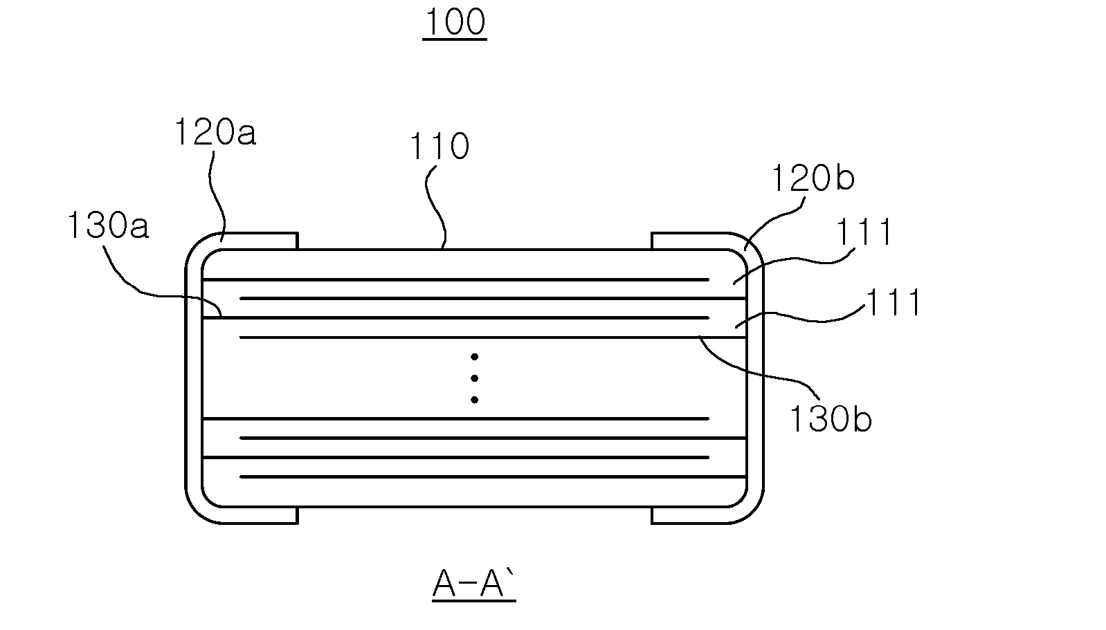
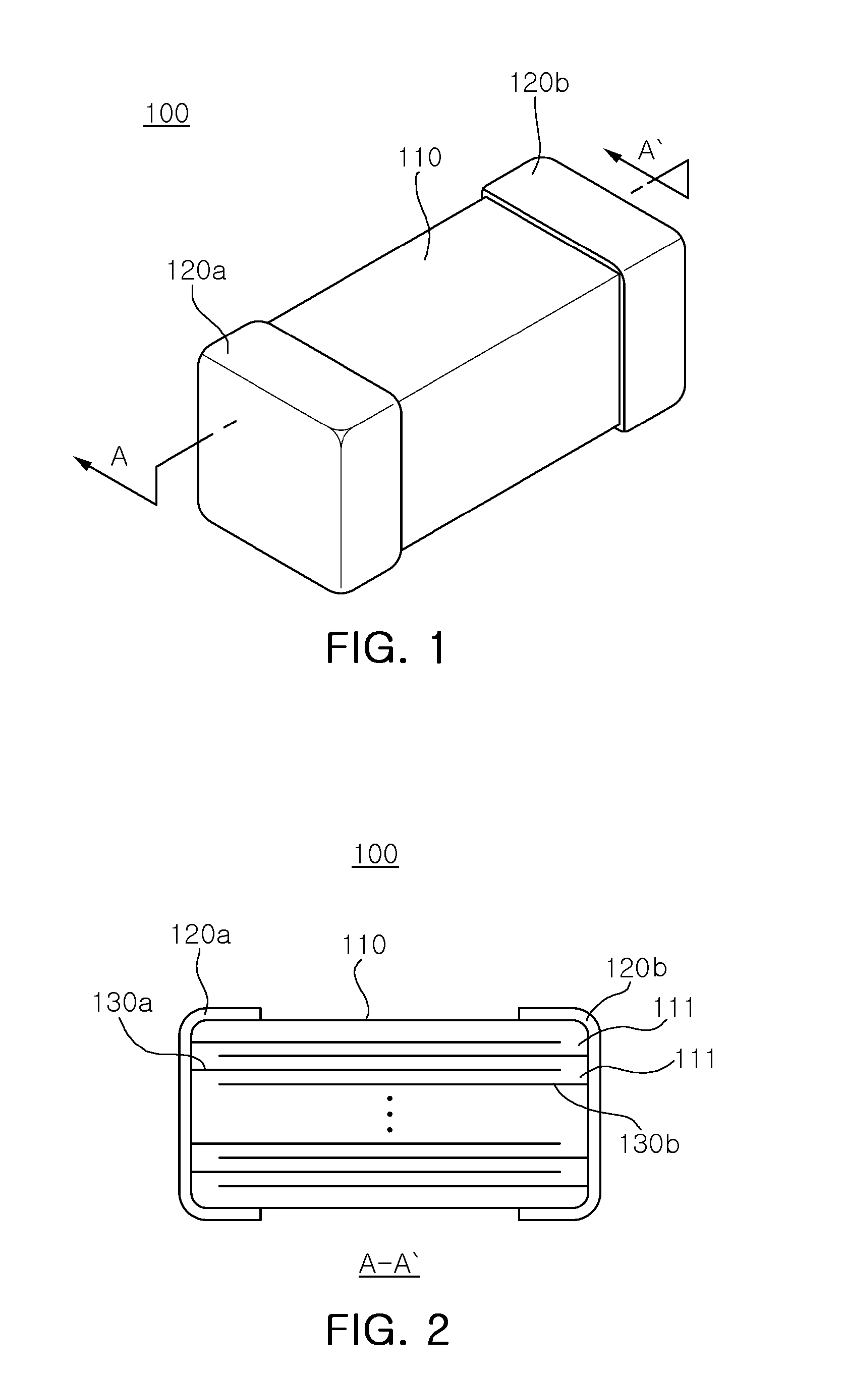
[0075]The molded ceramic sheet was printed with the Ni internal electrode. The top and bottom covers were manufactured by stacking the covering sheets each having the t...

Example

[0089]In addition, it could be appreciated from Examples 10 to 12 and Example 2 that as the sum of Mn and V, the first accessory component, is increased, the normal-temperature RC value and the high-temperature withstand voltage are increased and then, when the value of the first accessory component in the amount of thereof is excessively increased as in Example 12, these characteristics are rather decreased, under the same conditions that Dy2O3 is 0.3 mol % and CeO2 is 0.2 mol %.

[0090]Therefore, when at % amount of the first accessory component Mn and V is set to be x2 and at % amounts of the rare earth element and the Ce in the third accessory component are respectively set to be z and w, as compared with the BCTZ; the range of x2, z, and w in which the dielectric characteristic, the non-reduction, and the reliability are implemented, may be set to be 0.2≦x2≦1.4, 0.01≦z≦0.6, and 0.01≦z+w≦4x2.

[0091]Table 3 shows Examples of the dielectric composition in the X5R / X7R type MLCC in whi...

Example

[0098]That is, it could be appreciated from Examples 25, 27, 23, 29, and 31 that as the MgCO3 that is the second accessory component is not included (Example 25) or is gradually increased to 0.5 mol % (Example 27), 1.0 mol % (Example 23), 2.0 mol % (Example 29), and 3.0 mol % (Example 31), the at % concentration of Dy+Ce that is the third accessory component is increased 0.5 at % (Example 25), 2.5 at % (Example 27), 4.5 at % (Example 23), 8.5 at % (Example 29), and 12.5 at % (Example 31), and the normal-temperature RC value and the high-temperature withstand voltage is sharply reduced.

[0099]In addition, it could be appreciated that when the content of the MgCO3 that is the second accessory component is excessive as 3.0 mol % (Example 30), the firing temperature is increased and the permittivity and the high-temperature withstand voltage is poor.


PUM

PropertyMeasurementUnit
Thicknessaaaaaaaaaa
Substance countaaaaaaaaaa
Compositionaaaaaaaaaa

Abstract

There is provided a dielectric composition including: a base powder including BaTiO3; a first accessory component including a content (x1) of 0.1 to 1.0 at % of an oxide or a carbonate including transition metals, based on 100 moles of the base powder; a second accessory component including a content (y) of 0.01 to 3.0 at % of oxide or carbonate including a fixed valence acceptor element, based on 100 moles of the base powder; a third accessory component including an oxide or a carbonate including a Ce element (content of z at %) and at least one rare earth element (content of w at %); and a fourth accessory component including a sintering aid, wherein 0.01≦z≦x1+4y and 0.01≦z+w≦x1+4y based on 100 moles of the base powder.

Description

CROSS-REFERENCE TO RELATED APPLICATIONS[0001]This application claims the priority of Korean Patent Application No. 10-2011-0100772 filed on Oct. 4, 2011, in the Korean Intellectual Property Office, the disclosure of which is incorporated herein by reference.BACKGROUND OF THE INVENTION[0002]1. Field of the Invention[0003]The present invention relates to a dielectric composition and a ceramic electronic component including the same.[0004]2. Description of the Related Art[0005]Generally, electronic components using a ceramic material, such as a capacitor, an inductor, a piezoelectric element, a varistor, or a thermistor, include a ceramic element formed of a ceramic material, internal electrodes formed within the ceramic element, and external electrodes mounted on a surface of the ceramic element to be connected to the internal electrodes.[0006]Among ceramic electronic components, a multilayer ceramic capacitor (MLCC) includes a plurality of laminated dielectric layers, internal electr...

Claims


Application Information

Patent Timeline
IPC IPC(8): H01G4/12C04B35/468
CPCC04B35/4682H01G4/1227C04B2235/3215C04B2235/3217C04B2235/3224C04B2235/3225C04B2235/3229C04B2235/3236C04B2235/3239C04B2235/3241C04B2235/3262C04B2235/3267C04B2235/3272C04B2235/3275C04B2235/3279C04B2235/3281C04B2235/3284C04B2235/3418C04B2235/36C04B2235/442C04B2235/5445C04B2235/6025C04B2235/652C04B2235/656C04B2235/6582C04B2235/663H01G4/30H01G4/0085C04B2235/3208C04B35/01C04B35/468C04B35/495
Inventor YOON, SEOK HYUNPARK, JI YOUNGYOON, SUN HOKWON, SANG HOONKIM, CHANG HOON
Owner SAMSUNG ELECTRO MECHANICS CO LTD
Why Eureka
Try Eureka