
Chilled ammonia based co2 capture system with wash system and processes of use

a co2 capture and ammonia technology, applied in the direction of liquid degasification, membranes, separation processes, etc., can solve the problems of integrating stripper overhead heat, high cost, and high cost of ammonia recovery process, so as to reduce energy consumption, reduce ammonia slip, and efficiently recover ammonia slip

Active Publication Date: 2013-04-18
GENERAL ELECTRIC TECH GMBH
View PDF7 Cites 14 Cited by
  • Summary
  • Abstract
  • Description
  • Claims
  • Application Information

AI Technical Summary

Benefits of technology

This patent is about a system and process for purifying gas using a chilled ammonia-based system. The system includes a wash vessel for reducing ammonia slip, a separation unit for separating the washed liquid into two different streams, and a stripper system for further purifying the gas. The technical effects of the invention include reduced energy consumption and more efficient gas purification.

Problems solved by technology

The current ammonia recovery process from the stripper is an expensive process (approximately 20% heat duty of the main CO2 regenerator) in terms of both capital and operating cost because it is very difficult to integrate stripper overhead heat with the main regenerator network.

Method used


Image

  • Chilled ammonia based co2 capture system with wash system and processes of use
  • Chilled ammonia based co2 capture system with wash system and processes of use
  • Chilled ammonia based co2 capture system with wash system and processes of use

Examples


example 1

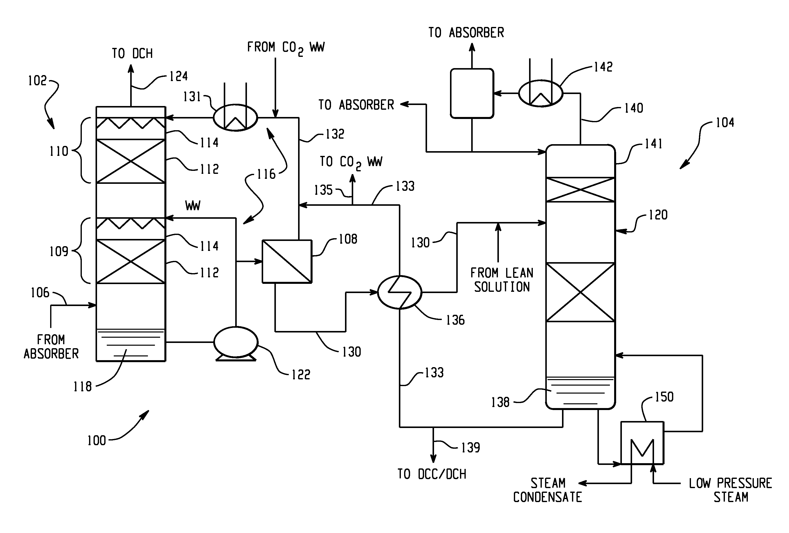
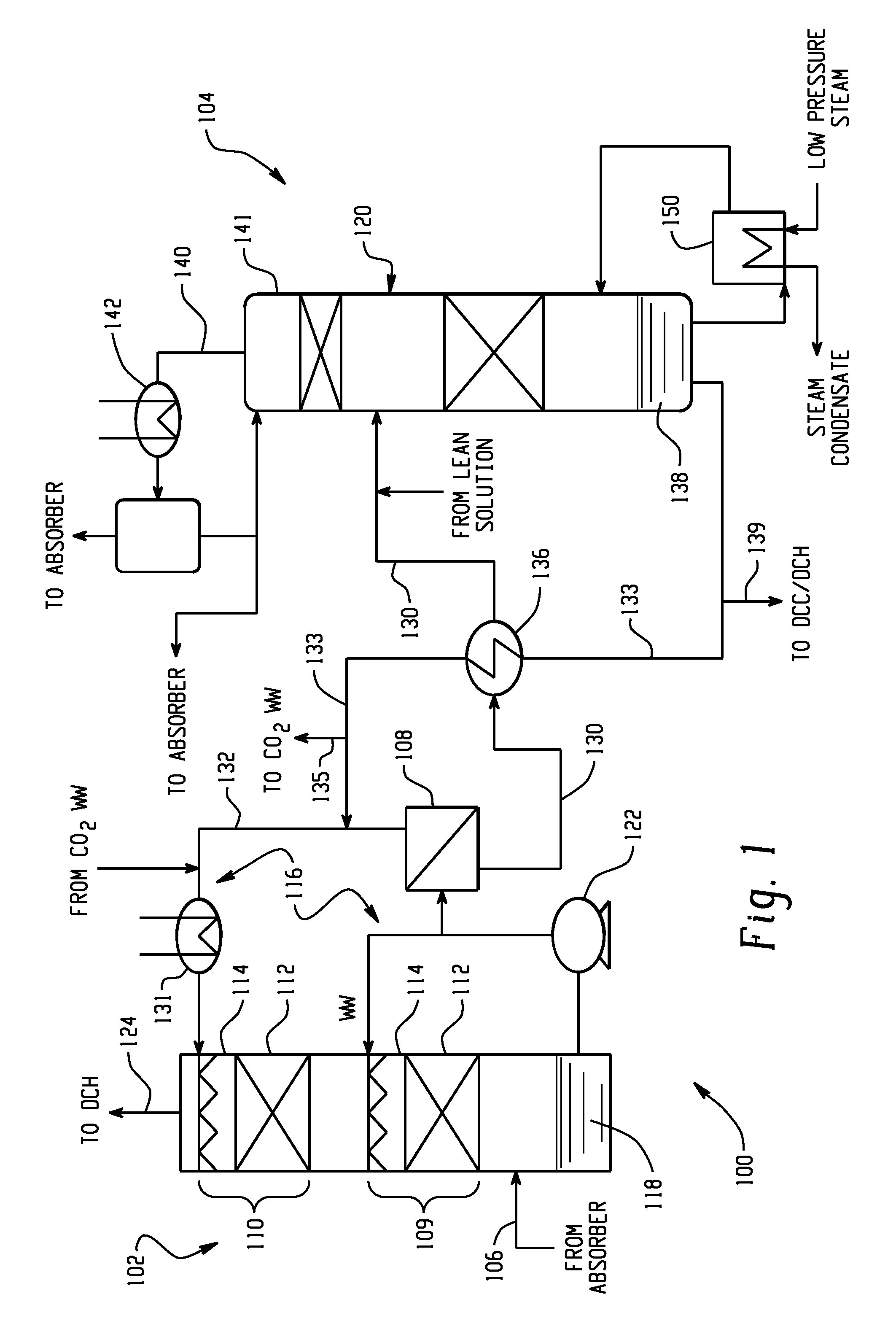
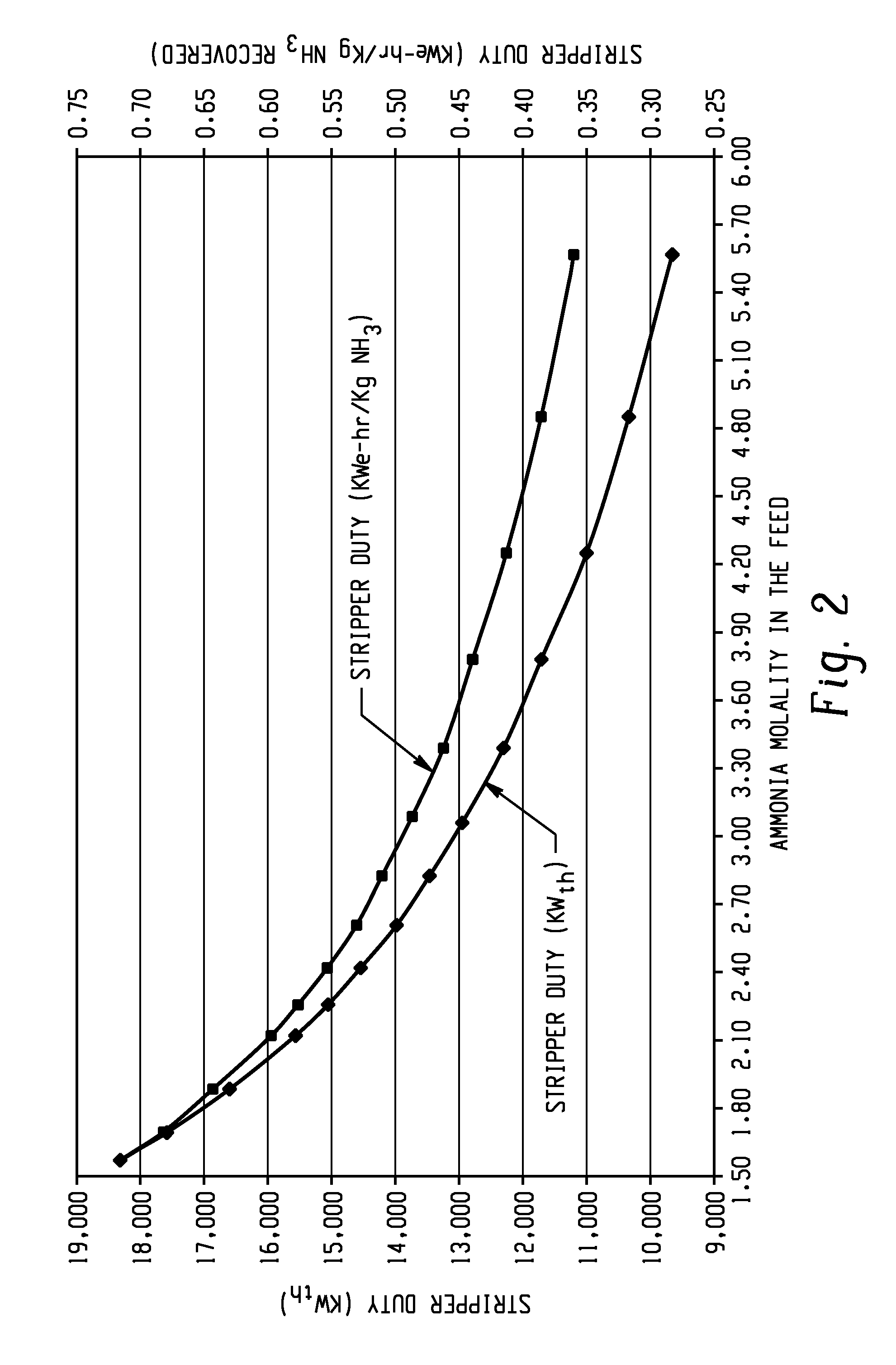
[0039]In this example, stripper duty as a function of ammonia molality was measured in terms of kilowatts thermal (KWth) and kilowatts electrical-hours per kilogram of ammonia recovered (KWe-hr / kg NH3 recovered). Inlet ammonia molality (m) was varied from about 1.50 to about 5.70 at a constant flow rate. The stripper feed had an Rvalue (moles NH3 / moles CO2) of 2.0, a stripper operating pressure of 1.7 bara, and a temperature of 110° C. The ammonia concentration of the liquid at the stripper bottom was at about 0.1 molar (M). FIG. 2 graphically illustrates stripper duty as a function of the ammonia molality. As shown in FIG. 2, greater than about 50% stripper duty KWe-hr / kg NH3 recovered can be reduced.

example 2

[0040]In this example, stripper power consumption was measured as a function of ammonia slip from an absorber. The stripper feed from the water wash vessel had an Rvalue (moles of NH3 / moles of CO2) of 2.0, a stripper operating pressure of 1.7 bara, and temperature of 110° C. The inlet ammonia containing flue gas entering the wash vessel was varied between about 1800 to about 11,500 parts per million by volume (ppmv) at a constant flow rate. The ammonia concentration of the liquid at the stripper bottom was at about 0.1 molar. FIG. 3 graphically illustrates stripper power consumption as a function of ammonia slip from the absorber during operation. As shown, increasing the amount of ammonia slip from the water wash vessel resulted in a lower specific stripper duty per Kg of ammonia recovered, thereby requiring lower power consumption requirements.

[0041]Advantageously, the high molarity retentate reduces the stripper steam consumption significantly as is evidenced by the data provided...


PUM

PropertyMeasurementUnit
temperatureaaaaaaaaaa

Abstract

Systems and processes for reducing the energy requirements of an ammonia recovery stripper in a chilled ammonia-based CO2 removal system. The systems and processes include a nanofiltration or reverse osmosis unit for physically separating the washed liquid from a wash vessel configured to receive an ammonia slip feed stream from the main absorber of the chilled ammonia-based CO2 removal system and provide first and second feed streams. Relative to the washed liquid from the wash vessel, the first feed stream has a decreased ammonia molarity whereas the second feed stream has an increased ammonia molarity. The second feed stream is then fed to the ammonia recovery stripper, which reduces steam consumption. The reduced steam consumption translates to significant energy savings, among numerous other advantages. Additionally, the systems and process provide a reduction of equipment sizes related to the stripper unit as may be desired in some applications.

Description

BACKGROUND[0001]The present disclosure generally relates to gas purification systems and processes of use, wherein absorbed ammonia and carbon dioxide are recovered. In particular, the present disclosure relates to wash systems and processes configured to utilize nanofiltration or reverse osmosis to reduce the steam duties of an ammonia recovery stripper for reducing the ammonia slip and other contaminants from a gas stream that has been subjected to an ammonia-based CO2 removal process.[0002]In conventional industrial technologies for gas purification, impurities, such as H2S, CO2 and / or COS are removed from a gas stream such as flue gas, natural gas, syngas or other gas streams by absorption in a liquid solution, e.g., in a liquid solution comprising ammonia and / or one or more amine compounds. The used liquid solution is subsequently regenerated in a regenerator column to release the impurities comprised in the solution, typically by countercurrent contacting with steam. The steam...

Claims


Application Information

Patent Timeline
Patent Type & Authority Applications(United States)
IPC IPC(8): B01D53/14B01D19/00
CPCB01D53/1418B01D53/1475Y02C10/04B01D61/025B01D61/027C02F1/20C02F1/441C02F1/442B01D2252/102C02F2101/16C02F2103/18B01D2311/04B01D2311/2626B01D3/007B01D3/145B01D19/0015Y02C10/06Y02P70/10Y02C20/40
Inventor DUBE, SANJAY KUMAR
Owner GENERAL ELECTRIC TECH GMBH
Learn More