Steel fuel conveying pipe
a conveying pipe and steel technology, applied in the field of pipes, can solve the problems of increasing the cost or impossibility of stable material supply, increasing the cost of product realization, increasing the cost, etc., and achieve the effect of significant improvement of reliability and a life of the gasoline direct-injection engine system
- Summary
- Abstract
- Description
- Claims
- Application Information
AI Technical Summary
Benefits of technology
Problems solved by technology
Method used
Image
Examples
example 1
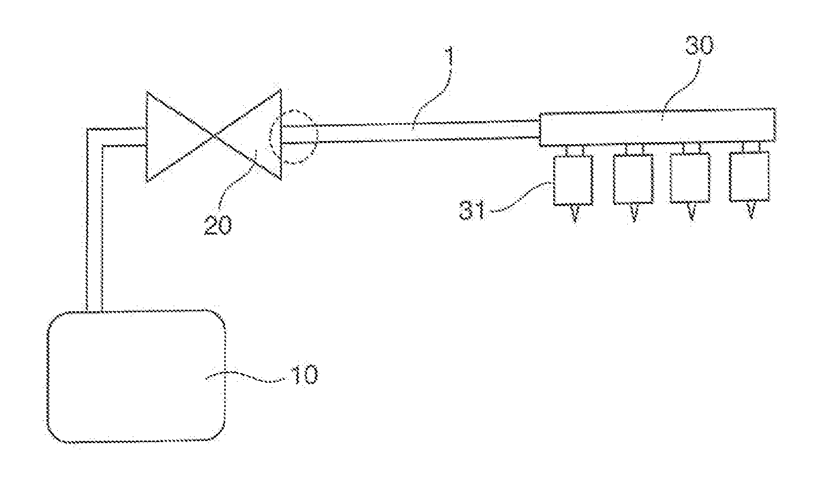
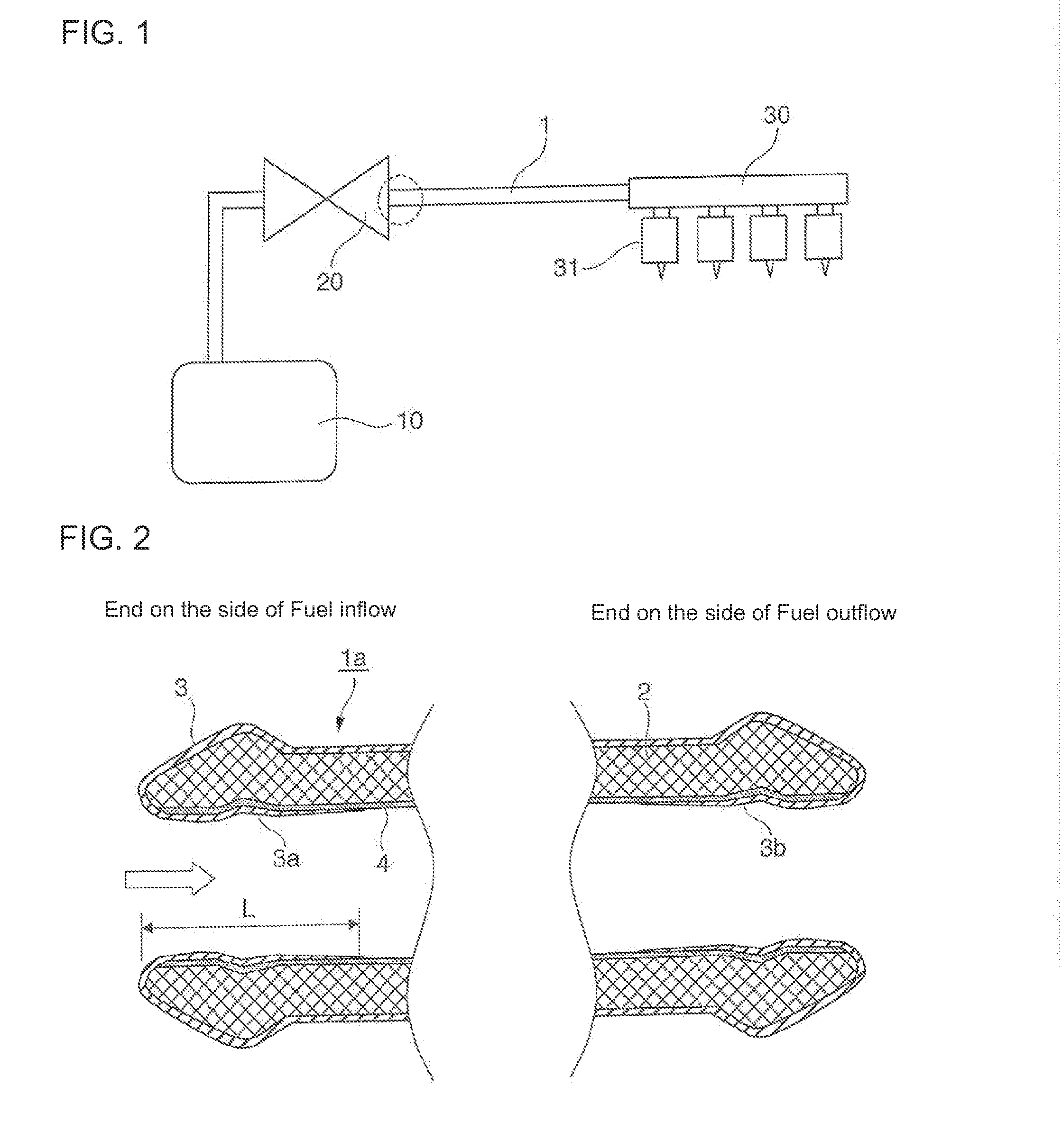
[0089]In the fuel conveying pipe 1a of the present invention having the structure shown in FIG. 2, a steel pipe for high pressure having an inner diameter of 5 mm (D=5 mm) was used as the pipe base material 2, the Ni-plated layer 4 was formed by applying Ni plating with a thickness of 10 μm to the whole inner face of the pipe material, and the anti-rust film layers 3a and 3b were then formed by setting a Zn-plated layer as the anti-rust film layer from an end of the pipe, setting the coating distance L of the anti-rust film layer to 10 mm (L=2D=10 mm) and applying Zn plating with a thickness of 0.1 to 8 μm up to the position of the coating distance L, so that a test material of the fuel conveying pipe was manufactured. The corrosion test to corrosive fuel was performed using the test material. The result of the test is shown in Table 1.
example 2
[0090]In the fuel conveying pipe 1a of the present invention having the structure shown in FIG. 2, a steel pipe for high pressure having an inner diameter of 8 mm (D=8 mm) was used as the pipe base material 2, the Ni-plated layer 4 was formed by applying Ni plating with a thickness of 10 μm to the whole inner face of the pipe material, and the anti-rust film layers 3a and 3b were then formed by setting a Zn—Ni layer as the anti-rust film layer from an end of the pipe, setting the coating distance L of the anti-rust film layer to 24 mm (L=3D=24 mm) and applying Zn—Ni alloy-plating with a thickness of 0.1 to 8 μm up to the position of the coating distance L, so that a test material of the fuel conveying pipe was manufactured. The corrosion test to corrosive fuel which was the test liquid was performed using the test material. The result of the test is shown in Table 1.
example 3
[0091]In the fuel conveying pipe 1a of the present invention having the structure shown in FIG. 2, a steel pipe for high pressure having an inner diameter of 3 mm (D=3 mm) was used as the pipe base material 2, a Ni-plated layer with a thickness of 5 μm was provided by non-electrolytic plating of NiP, and the anti-rust film layers 3a and 3b were then formed by setting a Sn—Zn alloy-plated layer as the anti-rust film layer on the inner face, setting the coating distance L of the anti-rust film layer to 9 mm (L=3D=9 mm) and applying Sn—Zn alloy plating with a thickness of 0.1 to 8 μm up to the position of the coating distance L, so that a test material of the fuel conveying pipe was manufactured. The corrosion test to corrosive fuel which was the test liquid was performed using the test material. The result of the test is shown in Table 1.
PUM
 Abstract
Description
Claims
Application Information
 - R&D
- Intellectual Property
- Life Sciences
- Materials
- Tech Scout
- Unparalleled Data Quality
- Higher Quality Content
- 60% Fewer Hallucinations
Browse by: Latest US Patents, China's latest patents, Technical Efficacy Thesaurus, Application Domain, Technology Topic, Popular Technical Reports.
© 2025 PatSnap. All rights reserved.Legal|Privacy policy|Modern Slavery Act Transparency Statement|Sitemap|About US| Contact US: help@patsnap.com


