Method and device for high resolution full field interference microscopy

a full-field interference, microscopy technology, applied in the direction of spectrum investigation, sensors, diagnostics, etc., can solve the problems of limiting the effective field of view, reducing the resolution of the cell, and proving it is more difficult to obtain in depth images of the optical section to a level of resolution

Active Publication Date: 2013-05-02
LLTECH MANAGEMENT
View PDF3 Cites 21 Cited by
  • Summary
  • Abstract
  • Description
  • Claims
  • Application Information

AI Technical Summary

Benefits of technology

[0022]According to a variant, the emission source is a source with variable spectral width, the processing unit making it possible to obtain tomographic images of slices of the sample of different thicknesses, the thickness of the slice being determined by the temporal coherence length of the source. This configuration makes it possible to adjust the three-dimensional magnification of the device by acting both on the transverse and axial magnification.

Problems solved by technology

For other tissues of the human body, which are more dense, and have large effective scattering cross-sections, it has proven more difficult to obtain in depth images of optical sections to a level of resolution of a cell.
However, when a three-dimensional examination of a biological tissue is required for a diagnosis for example, the quantity of data that has to be acquired becomes gigantic.
Because of its rectangular geometry, the camera generally limits the effective field of view to an area slightly less than the field of view of the objective.
However, such a method is slow and even by using cameras with millions of pixels, recording such images may take several hours.
This processing time is detrimental, both for in-vivo examination applications, for example in dermatology, and for ex-vivo examination applications, for example for the examination of a tumor.
Moreover, the information storage capacity has to be extremely large.
The issue of improving the data acquisition time and of limiting the quantity of information to be stored therefore arises, as a corrolorary to the acceleration in the development of devices for very-high-resolution imaging in tissues, of which the FF-OCT technique is a perfect illustration.

Method used


Image

  • Method and device for high resolution full field interference microscopy
  • Method and device for high resolution full field interference microscopy
  • Method and device for high resolution full field interference microscopy

Examples


Embodiment Construction

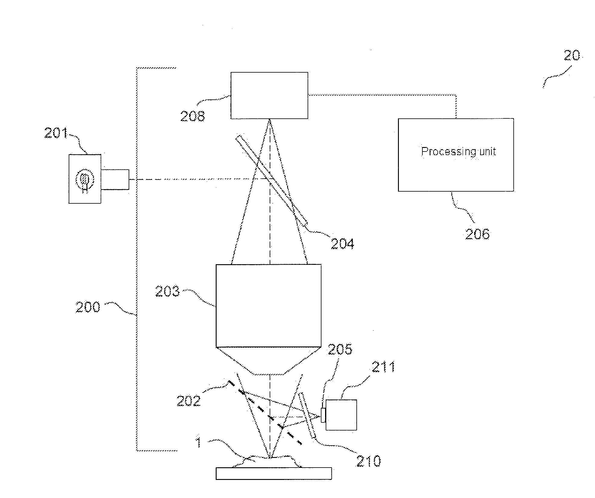
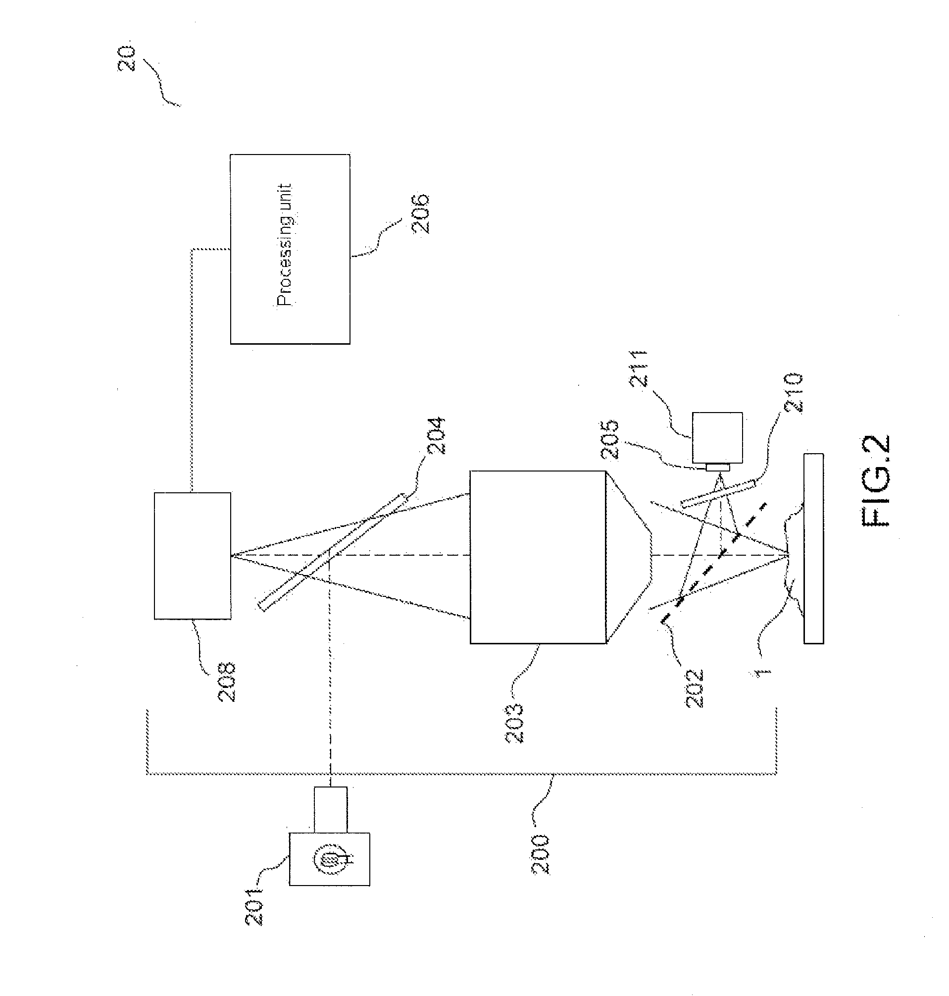
[0038]FIG. 2 represents a device 20 for three-dimensional imaging of a volumic and scattering sample 1 according to an exemplary embodiment of the invention. The sample is, for example, a biological tissue. It generally comprises an imaging interferometer 200 with variable magnification and a processing unit 206. In this example, the imaging interferometer has a Michelson-type configuration. It is illuminated by a source 201 with low spatial and temporal coherence, for example a halogen-type white-light source. The imaging interferometer 200 comprises a multichannel acquisition device 208, for example a CCD or CMOS camera, a first beam splitter element 204 that makes it possible to send into the interferometer the wave emitted by the source, a microscope objective 203, a second beam splitter element 202 for forming the two arms of the interferometers. The beam splitter element 202 is, for example, a pellicle beamsplitter in order to limit the geometric aberrations that may result fr...


PUM


Abstract

According to one aspect, the invention relates to a device (20) for three-dimensional imaging by full-field interferential microscopy of a volumic and scattering sample (1) comprising an emission source (201) for emitting an incident wave with low temporal coherence, an imaging interferometer (200) of variable magnification, allowing for the acquisition of at least one first and one second interferometric images resulting from the interference of a reference wave obtained by reflection of the incident wave on a reference mirror (205) and an object wave obtained by backscattering of the incident wave by a slice of the sample at a given depth of the sample, the at least two interferometric images having a phase difference obtained by varying the relative path difference between the object and reference arms of the interferometer, a processing unit (206) for processing said interferometric images making it possible to obtain a tomographic image of said slice of the sample, means for axially displacing the interferometer relative to the sample allowing for the acquisition of tomographic images for slices at different depths of the sample and means for varying the magnification of the imaging interferometer allowing for the acquisition of interferometric images of a slice of the sample for different magnification values.

Description

TECHNICAL FIELD OF THE INVENTION[0001]The present invention relates to a method and a device for three-dimensional imaging by full-field interferential microscopy, notably for cellular imaging.STATE OF THE ART[0002]The optical microscopy technique based on the acquisition of images with a very low depth of field (of around 1 μm) called optical sectioning, is highly developed in biology and in the medical field, fields in which the strong scattering of the tissues being observed makes the use of conventional microscopy useless.[0003]Among the techniques used for high-resolution 3D imaging (resolution of around 1 micron), laser scanning confocal microscopy, based on the selective illumination of a minimum volume in the object and the detection of the optical response originating only from this volume by geometrical discrimination, is widely used. The use of lenses with strong numerical aperture (numerical aperture typically between 0.8 and 1.4) makes it possible to obtain a low depth ...

Claims


Application Information

Patent Timeline
Patent Type & Authority Applications(United States)
IPC IPC(8): G01B9/02
CPCA61B5/0066A61B2562/046G01B11/2441G01J3/0208G01J3/0237G01B9/02048G01J3/2823G01J3/45G02B21/14G01B9/02091G01B9/02057G01J3/10
Inventor BOCCARA, ALBERT CLAUDEHARMS, FABRICELE CONTE CHRESTIEN DE POLY, BERTRAND
Owner LLTECH MANAGEMENT
Why Eureka
Try Eureka