Energy recovery in manufacture of sulfuric acid

a technology of energy recovery and sulfuric acid, which is applied in the field of energy recovery in the manufacture of sulfuric acid, can solve the problems of inability to control the acid concentration much, the proportion of dilution water provided by steam injection into the conversion gas is limited to about 33%, and the heat absorption cannot be recovered in any useful form other than district heating, so as to enhance the energy recovery and enhance the energy recovery effect. , the effect of preserving the control of corrosion

Active Publication Date: 2013-05-09
MECS
View PDF0 Cites 6 Cited by
  • Summary
  • Abstract
  • Description
  • Claims
  • Application Information

AI Technical Summary

Benefits of technology

[0012]In the contact sulfuric acid processes of the present invention, enhanced recovery of energy is obtained from the absorption zone wherein SO3 is absorbed into sulfuric acid. Energy is recovered in useful form, for example, as intermediate pressure steam. Enhanced energy recovery is achieved while preserving control of corrosion at the heat exchange surfaces that are wetted with absorption acid, and without excessive or intolerable generation of acid mist. The quantity of intermediate pressure steam than can be generated from the absorption loop can be increased significantly, e.g., by up to 25% or more, compared to commercial processes in which no more than about 33% of dilution water has been supplied in the form of water vapor contained in the gas stream entering the absorber.

Problems solved by technology

Prior to that time, the heat of absorption could not be recovered in any useful form other than for district heating, because materials of construction issues limited the temperature at which an SO3 absorber could be operated.
The latter option is criticized as making it impossible to control the acid concentration much above the azeotrope, i.e., between 98.8% and 99.2% with consequent adverse corrosion effects.
Because of various concerns, including corrosion of the absorption acid heat exchanger and generation of acid mist, the highest proportion of dilution water provided by steam injection into the conversion gas has been limited to about 33% in industrial operations within the United States.
In both dry gas and wet as operations, including but not limited to steam injection, mist has been a complex and often baffling problem.
Where the heat recovery absorber functions as an interpass absorber, mist in the exit gas stream may deposit on downstream surfaces causing significant corrosion.

Method used


Image

  • Energy recovery in manufacture of sulfuric acid
  • Energy recovery in manufacture of sulfuric acid
  • Energy recovery in manufacture of sulfuric acid

Examples


example 1

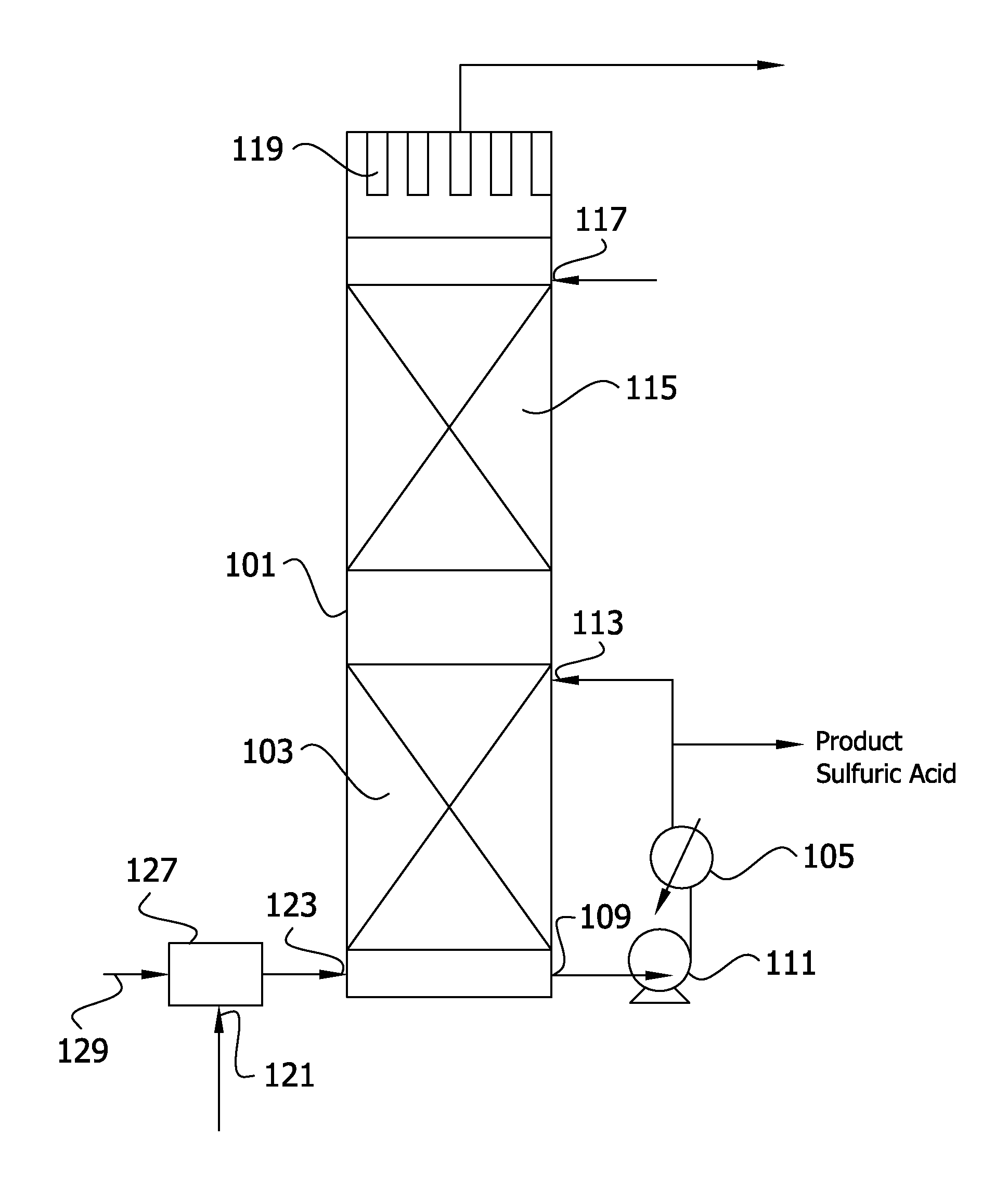
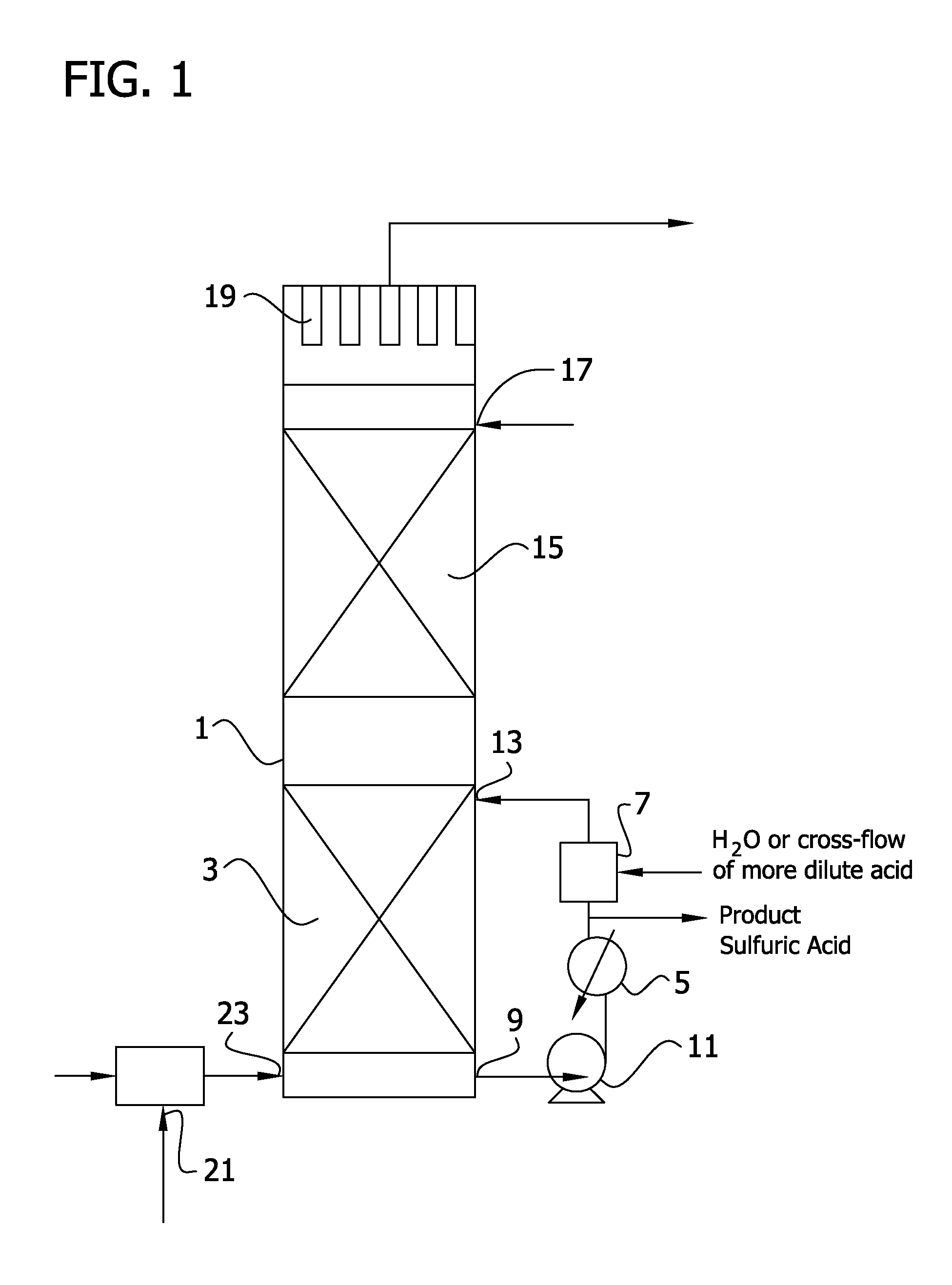
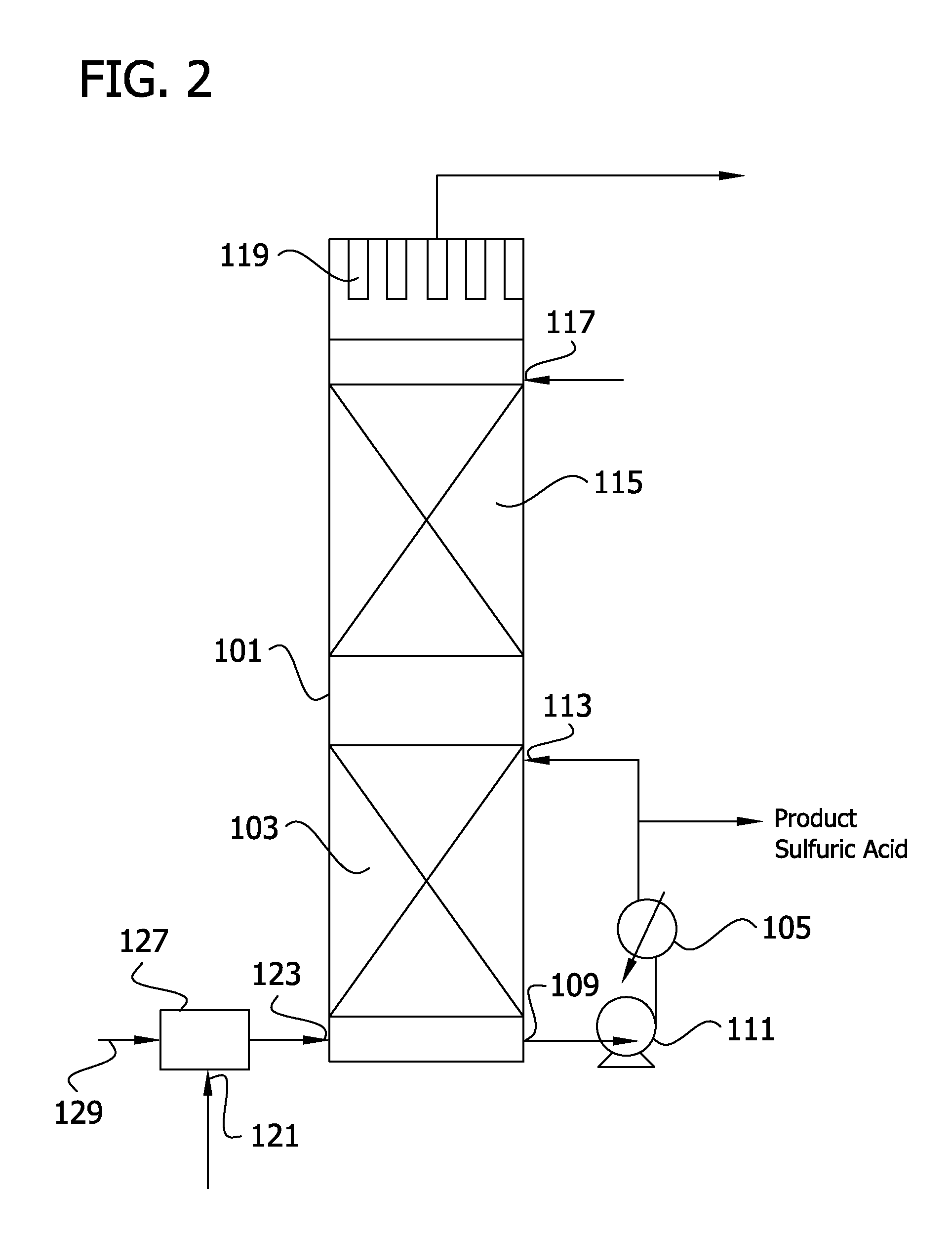
[0209]In the process as illustrated in FIG. 2, a dry SO3 conversion gas stream at a temperature of 165° C., flowing at rate of 50 standard cubic meter per second (106,000 standard cubic feet per minute), and containing 11.6% by mole SO3, 0.6% by mole SO2, 4.2% by mole O2, and 83.6% by mole N2 is passed through an indirect heat exchanger to recover the heat of reaction of SO2 and SO2 by transfer to superheated steam. The SO3 gas stream exits the steam superheater at 165° C. is delivered at an absolute pressure of about 0.2 MPascals (18 psia) to a water vapor injection zone 127 as shown in FIG. 2. In injection zone 127, steam at a pressure of at least about 0.1 MPascals (1 bar) above the pressure in the gas line is injected into the gas stream at 4.3 Kg / s (570 lbs / min), sufficient so establish a molar ratio of equivalent water vapor to equivalent SO3 in the gas stream to about 0.95 to 1.0. In the water vapor injection zone, the vapor phase heat of reaction of SO3 and water vapor incre...

example 2

[0213]In a process as illustrated in FIG. 3, operation is similar to that of Example 1 except that the primary absorption zone is operated at a higher L / G and there is a correspondingly lower acid side temperature rise through the primary absorption zone and lower acid side temperature drop through heat exchanger 105. Absorption acid exiting principal absorption acid heat exchanger 105 is divided into a primary absorption acid stream that is returned to the primary absorption zone via acid return inlet 113, a net acid production stream, and a secondary absorption acid stream that is cooled to 60° C. in auxiliary acid heat exchanger 131. Alternatively, the acid stream exiting heat exchanger 105 is divided into a primary absorption acid stream and an auxiliary acid stream that passes through heat exchanger 131 and is thereafter divided into the net product scream and the secondary acid stream that is returned to secondary absorption zone 115.

[0214]In the embodiment of FIG. 3, recircul...

example 3

[0216]In the process of FIG. 9, a wet SO2 stream from a spent acid plant containing excess oxygen is passed through a catalyst bed to convert SO2 to SO3. Additional water vapor is introduced into the gas stream in steam injection zone 227 to produce a gas stream that enters heat recovery tower 101 at inlet 123 and flows into primary absorption zone 103 at a temperature of 315° C. As introduced into the absorption zone after steam injection, the conversion gas flows at 103 Kg mole / s (13,623 lb moles / hr) and comprises 0.4 volume % SO2, 5.4 volume % SO3, 2.3 volume % oxygen, 72.7 volume % nitrogen, 5.6 volume % water vapor, 11 volume % CO2 and 2.5 volume % H2SO4 Absorption acid leaves the primary absorption zone at a strength of 99.5%, a flow rate of 107 Kg mole / s (14,100 lb moles / hr) and a temperature of 204° C. After passage through heat exchanger 105, the acid stream is divided to provide a recirculated acid stream that is returned to heat recovery absorption zone 103 and an auxilia...


PUM


Abstract

This invention relates to the recovery of energy in the manufacture of sulfuric acid, and more particularly to enhanced recovery of energy from the absorption of wet SO3 in sulfuric acid. The invention is further directed to control of mist formation during SO3 absorption, and of the sulfuric acid mist content of the gas stream leaving the SO3 absorption step in a process wherein SO3 absorption energy is recovered from absorption acid in useful form.

Description

[0001]This invention relates to the recovery of energy in the manufacture of sulfuric acid, and more particularly to enhanced recovery of energy from the absorption of wet SO3 in sulfuric acid. The invention is further directed to control of mist formation during SO3 absorption, and of the sulfuric acid mist content of the gas stream leaving the SO3 absorption step in a process wherein SO3 absorption energy is recovered from absorption acid in useful form.[0002]Twenty five years ago technology was developed for recovering in useful form the heat of absorption of SO3 in sulfuric acid. Prior to that time, the heat of absorption could not be recovered in any useful form other than for district heating, because materials of construction issues limited the temperature at which an SO3 absorber could be operated. Absorption acid coolers constructed of stainless steel were typically operated at a maximum inlet temperature in the neighborhood of 110° C.[0003]U.S. Pat. Nos. 4,576,813 and 4,67...

Claims


Application Information

Patent Timeline
Patent Type & Authority Applications(United States)
IPC IPC(8): C01B17/775
CPCC01B17/775C01B17/7655Y10T137/0402Y02P20/129C01B17/74B01D53/1406B01D53/1412B01D53/1425B01D53/78G05D27/00Y02P20/10
Inventor VERA-CASTANEDA, ERNESTO
Owner MECS
Why Eureka
Try Eureka