High-frequency coil and magnetic resonance imaging device employing same

a high-frequency coil and magnetic resonance imaging technology, applied in the field of magnetic resonance imaging apparatus, can solve the problems of significant increase in production cost, significant reduction of irradiation efficiency of high-frequency magnetic field, uneven contrast in image obtained, etc., and achieves the effect of reducing significantly the irradiation efficiency and homogeneity in the irradiation distribution, increasing production cost and large examination spa

Active Publication Date: 2013-05-16
FUJIFILM HEALTHCARE CORP
View PDF9 Cites 26 Cited by
  • Summary
  • Abstract
  • Description
  • Claims
  • Application Information

AI Technical Summary

Benefits of technology

[0026]According to the present invention, it is possible to reserve large examination space in the tunnel type MRI apparatus, without increasing production cost nor reducing significantly the irradiation efficiency and homogeneity in the irradiation distribution within an imaging region.

Problems solved by technology

This is because, if the distribution of the irradiation strength is imhomogeneous, a difference may occur in the excited state of the nuclear spins depending on portions within the test subject, and this causes contrast unevenness and / or artifacts in the image being obtained.
However, size-up of the inner diameter of the tunnel-type static magnetic field magnet may cause a significant increase of production cost.
However, if the RF shield is placed closer to the RF coil, the RF shield current flowing on the RF shield is increased so as to cancel the high frequency magnetic field, and eventually, the irradiation efficiency of the high frequency magnetic field is significantly reduced.

Method used


Image

  • High-frequency coil and magnetic resonance imaging device employing same
  • High-frequency coil and magnetic resonance imaging device employing same
  • High-frequency coil and magnetic resonance imaging device employing same

Examples


first embodiment

[0075]Hereinafter, the first embodiment to which the present invention is applied will be explained. In all the following figures for explaining the embodiments of the present invention, the constituents having the same function are labeled the same, and tedious explanations will not be made.

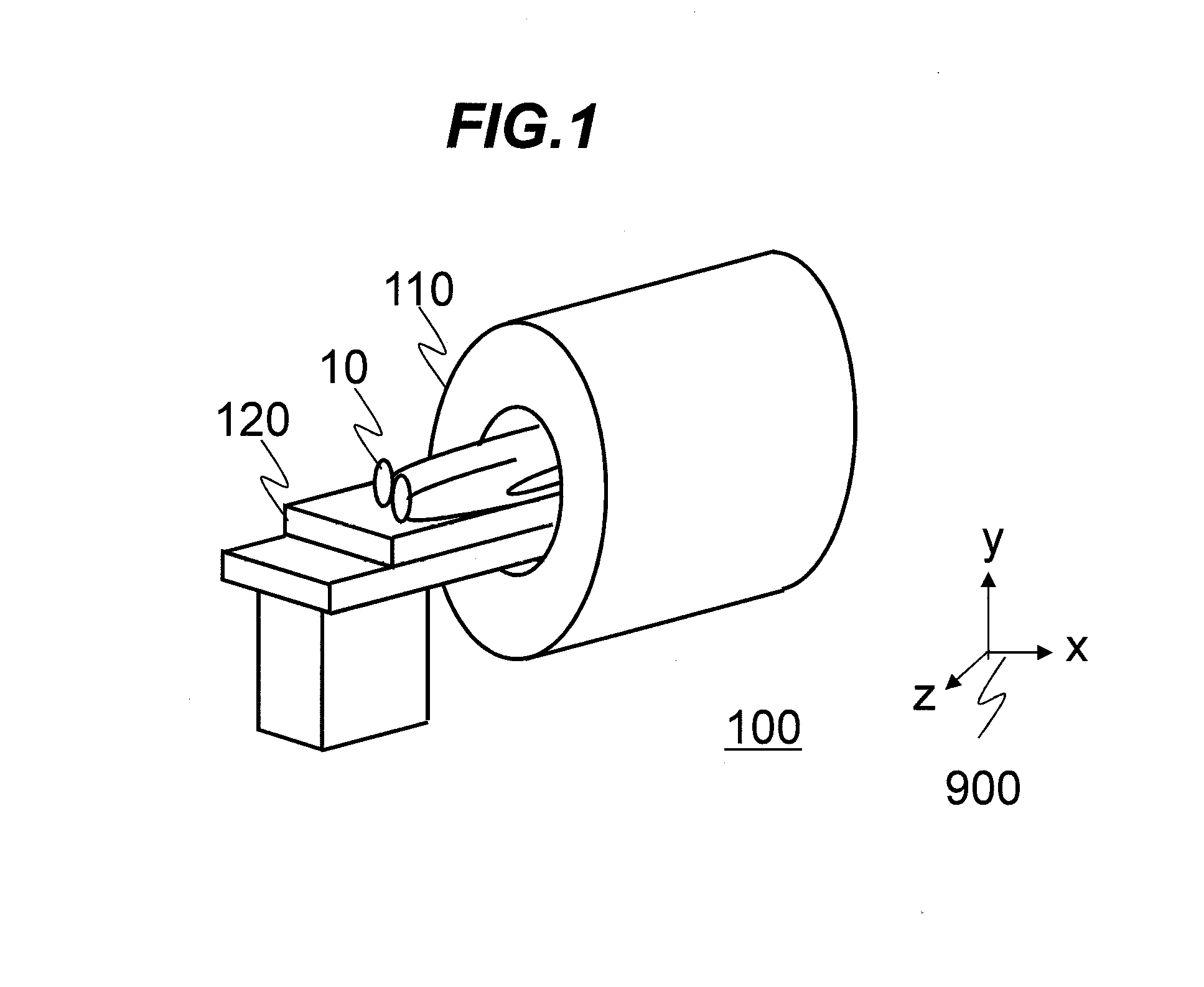
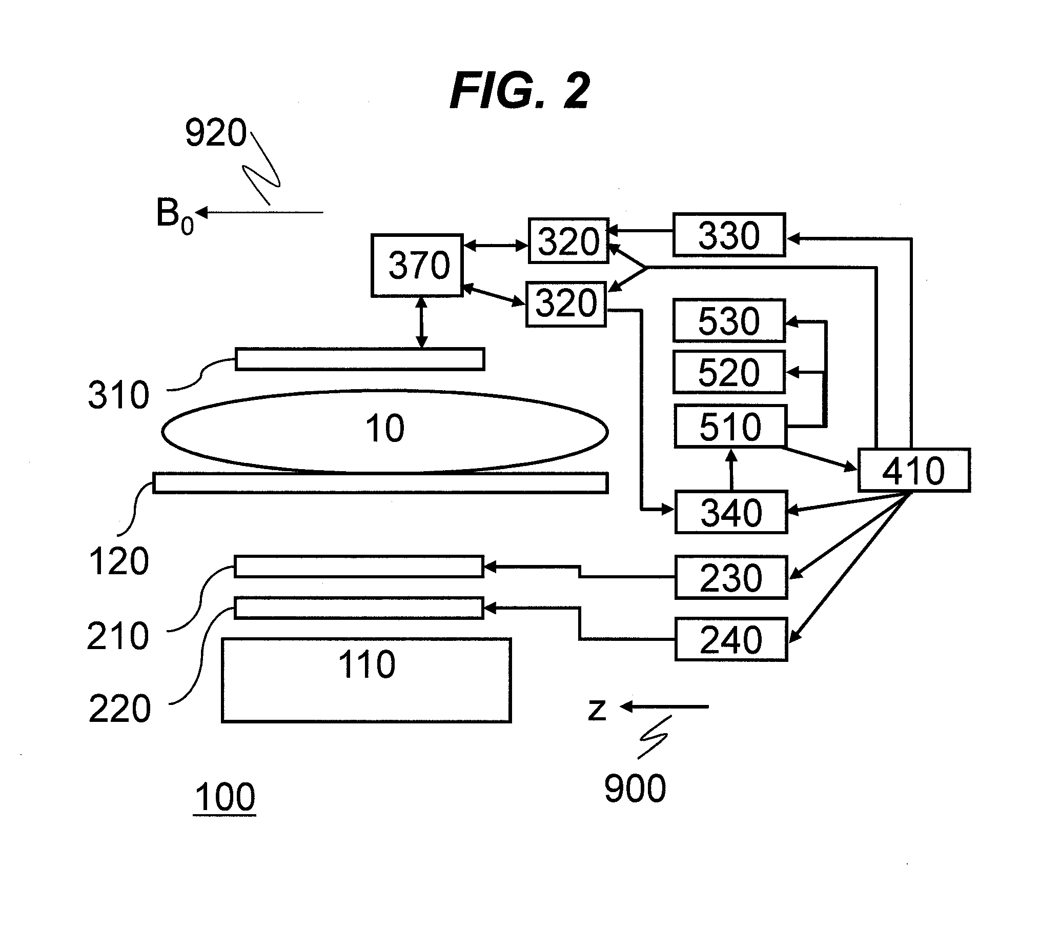
[0076]Firstly, the overall structure of the MRI apparatus according to the present embodiment will be explained. FIG. 1 is an overview of the MRI apparatus according to the present embodiment, and the z-axis direction of the coordinate system 900 in the figure indicates a direction of the static magnetic field. The MRI apparatus 100 according to the present embodiment is provided with a magnet 110 intended for a horizontal magnetic field system, and a patient table 120. The test subject 10 is inserted into the imaging space within the pore of the magnet 110, in the state being laid on the patient table 120, and an image is taken. In the present specification, hereinafter, the static magnetic fie...

second embodiment

[0141]Next, a second embodiment to which the present invention is applied will be explained. The MRI apparatus of the present embodiment is basically the same as that of the first embodiment. However, the RF shield, the first RF coil and the second RF coil, provided in the RF coil device, are different in shape. Hereinafter, an explanation will be made as to the present embodiment, focusing on the configuration being different from the first embodiment. Also in the present embodiment, the orientation of the static magnetic field generated by the magnet 110 of the horizontal magnetic field system is assumed as the z-axis direction of the coordinate system 900.

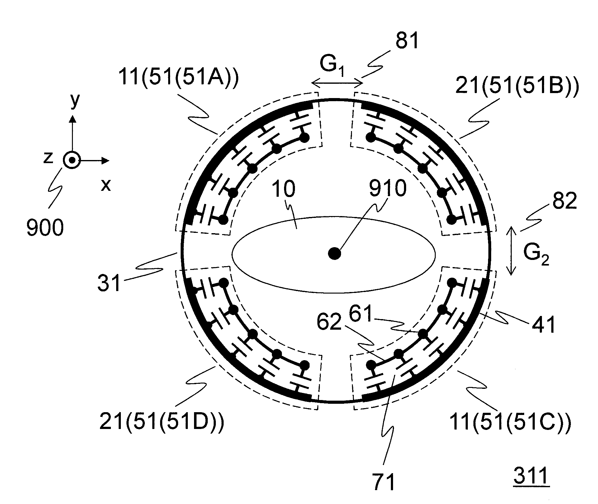
[0142]FIG. 14A and FIG. 14B illustrate a configuration of an RF coil device 313 according to the present embodiment. This RF coil device 313 is used as the transceive coil 310 as shown in FIG. 2. FIG. 14A illustrates the RF coil device 313 viewed in the direction of the central axis 910, FIG. 14B illustrates a partial elliptic c...

third embodiment

[0190]Next, the third embodiment to which the present invention is applied will be explained. The MRI apparatus of the present embodiment is basically the same as the second embodiment. However, an RF coil device 314 used as the transceive coil 310 of the MRI apparatus according to the present embodiment is provided with a magnetic coupling adjuster for adjusting magnetic coupling between the first RF coil 12 and the second RF coil 22, in addition to the RF coil device 313 of the second embodiment. Hereinafter, the present embodiment will be explained, focusing on the configuration different from the second embodiment. Also in the present embodiment, the orientation of the static magnetic field 920 generated by the magnet 110 of horizontal magnetic field system is assumed as the z-axis direction of the coordinate system 900.

[0191]FIG. 19A and FIG. 19B illustrates a configuration of the RF coil device 314 of the present embodiment. This RF coil device 314 is used as the transceive co...


PUM


Abstract

A technique is provided to reserve large examination space in the tunnel type MRI apparatus, without increasing production cost nor reducing significantly irradiation efficiency and homogeneity in an irradiation distribution within an imaging region. The present invention provides an RF coil unit in which four partial cylindrical coils are placed with a gap therebetween in the circumferential direction inside a cylindrical RF shield, in such a manner that two pairs of the partial cylindrical coils are opposed to each other, and magnetic fields produced by the individual partial cylindrical coils are combined, thereby producing a circularly polarized wave field or an elliptically polarized wave field. The partial cylindrical coil is provided with a partial cylindrical conductor, multiple first conductors substantially parallel with the central axis of the RF shield, multiple capacitors connecting both ends of the first conductors with the partial cylindrical conductor, and a second conductor adjacent to at least one of the ends of the first conductor. The partial cylindrical coils are respectively provided with high frequency signals having a desired amplitude ratio and phase difference, while a reference frequency thereof being identical.

Description

TECHNICAL FIELD[0001]The present invention relates to a magnetic resonance imaging (MRI) apparatus, and more particularly, it relates to a high frequency coil for electromagnetic wave irradiation and detection of a nuclear magnetic resonance signal.BACKGROUND ART[0002]The MRI apparatus is a medical diagnostic imaging apparatus which produces magnetic resonance in a nuclear spin within any slice passing transversely across an examination target, and obtains a tomographic image within the slice based on nuclear magnetic resonance signals being generated. When a high frequency coil (RF coil) irradiates a test subject placed in a static magnetic field with a high frequency magnetic field, while applying a gradient magnetic field, a nuclear spin within the test subject, for example, a nuclear spin of a hydrogen atom is excited. When the excited nuclear spin returns to the equilibrium state, a circularly polarized wave field is generated as a nuclear magnetic resonance signal. The RF coil...

Claims


Application Information

Patent Timeline
Patent Type & Authority Applications(United States)
IPC IPC(8): G01R33/34
CPCA61B5/055G01R33/34046G01R33/34084G01R33/3453G01R33/34G01R33/3657G01R33/3678G01R33/422G01R33/365
Inventor SOUTOME, YOSHIHISABITO, YOSHITAKATAKEUCHI, HIROYUKITAKAHASHI, TETSUHIKOOCHI, HISAAKIHABARA, HIDETA
Owner FUJIFILM HEALTHCARE CORP
Why Eureka
Try Eureka