Lattice

a technology of ligaments and joints, applied in the field of medical implants, can solve the problems of clinically significant narrowing of the artery, increased size and thickness, or even complete occlusion, and achieve the effect of large differences in mechanical properties and pulsatile complian

Active Publication Date: 2013-05-23
WL GORE & ASSOC INC
View PDF3 Cites 60 Cited by
  • Summary
  • Abstract
  • Description
  • Claims
  • Application Information

AI Technical Summary

Benefits of technology

[0011]In another embodiment, a prosthesis is provided that is configured to have pulsatile compliance. The prosthesis has a stent (i.e. a self-expanding stent), and can have a distal end and / or proximal end flared such that a diameter at an end of the stent is greater than a diameter defined in the center portion of the stent. The prosthesis further has a lattice defining a plurality of openings. These two components of the prosthesis have large differences in mechanical properties. The lattice can be very elastic or flexible, and the stent is typically very stiff in comparison. Thus, the combination produces an elastic response within the physiological pressure range of a natural vessel such as a blood vessel including for example a diseased blood vessel. In an embodiment, the combination can produce a non-linear elastic response within the physiological pressure range of a natural vessel. This characteristic of pulsatile expansion and contraction of host vessels requires fine mechanical compliance of the prosthesis, i.e., a close mimicking by the prosthetic device of the mechanics and timing of the natural vessel distending and reshaping under change in blood pressure. An elastomeric lattice covering on the outer surface of a stent embodiment provides an elastic constraining force to the stent (i.e. inward force) while the stent can provide an expansion force (i.e. outward force). This can be beneficial in avoiding draping of the lattice covering into the luminal space of the stent while it may additionally provide pulsatile compliance.

Problems solved by technology

Over time, the plaque can increase in size and thickness and can eventually lead to clinically significant narrowing of the artery, or even complete occlusion.

Method used


Image

  • Lattice
  • Lattice
  • Lattice

Examples


example 1

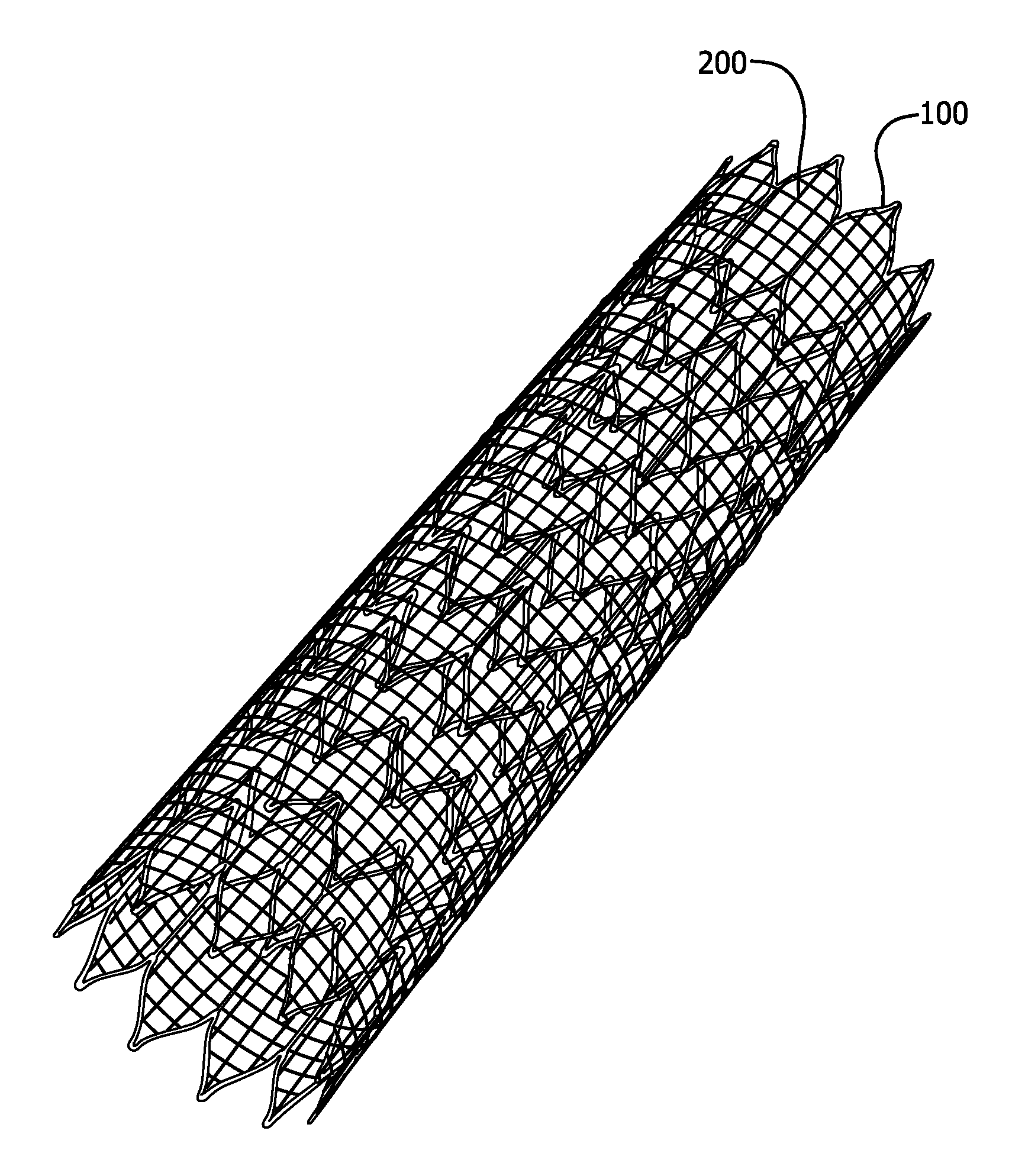
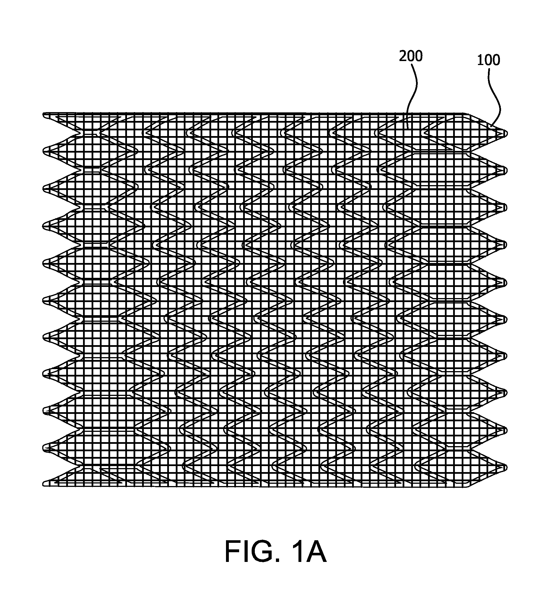
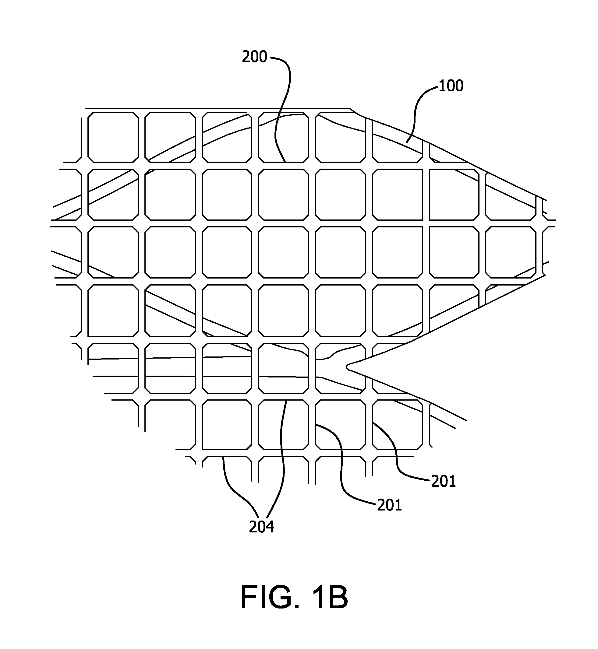
[0138]A lattice of the type shown in FIGS. 1A and 2B with square-shaped openings is prepared. A mandrel is wrapped with an ePTFE film with a discontinuous FEP coating to a thickness of approximately 0.05 mm. The film-mandrel assembly is placed into an oven at 320° C. for 12 minutes to bond the layers. The assembly is removed from the oven and allowed to cool at room temperature to provide an ePTFE tube. Using a CO2 laser, a pattern of regular square openings is cut into the tube. The openings are square-shaped with a size of less than about 0.5 mm. The width of the lattice segments is greater than about 0.05 mm (see FIG. 1B). The prepared square shaped lattice is placed in a convection oven set at 370° C. for 12 minutes. The material shrinks during heating to form squares that are approximately 0.5 mm diameter inscribed circle and lattice segments that are approximately 0.05 mm wide.

example 2

[0139]A lattice of the type shown in FIGS. 1B and 2C with diamond-shaped openings is prepared. An oversized mandrel that is approximately 25% larger than the nominal stent diameter is wrapped with an ePTFE film with a discontinuous FEP coating to a thickness of approximately 0.05 mm.

[0140]The film-mandrel assembly is placed into an oven at 320° C. for 12 minutes to bond the layers. The assembly is removed from the oven and allowed to cool at room temperature to provide an ePTFE tube. Using a CO2 laser, a pattern of slits approximately 40% longer than the final inscribed circle diameter are oriented transverse to the longitudinal axis of the mandrel are cut into the tube. The tube with slits is removed from the mandrel and tensioned over the nominal stent diameter mandrel and the slits open to form diamond shapes. The tube ends are temporarily fixed to length on the mandrel by ePTFE tape. The assembly is then placed into a convection oven set at 370° C. for 12 minutes. The material s...

example 3

[0141]A stent is powder coated with a thin layer of FEP powder (DuPont® FEP Fluoropolymer Resin, Product Type 5101) in a tabletop blender within which the stent is suspended. After the stent is placed within the blender with FEP powder, the blender is activated. The powder disperses into the volume of the blender chamber and the stent is powder coated. After approximately 3 seconds, the stent is removed, and is placed into a convection oven set at 320° C. for 5 minutes. After this time, the stent is removed and allowed to air cool.

[0142]The stent is then placed on a mandrel having an outer diameter approximately equal to the inner diameter of the stent. The mandrel is covered on its outer diameter with polyimide film. To temporarily fix the stent to the mandrel, the stent is placed in a convection oven set at 320° C. for 4 minutes.

[0143]After removal from the oven and cooling of the stent and mandrel assembly, a square-shaped opening lattice according to Example 1 is coaxially posit...


PUM


Abstract

The invention relates to medical devices and methods of using them. The devices are prostheses which can be percutaneously deliverable with (or on) an endovascular catheter or via other surgical or other techniques and then expanded. The prostheses are configured to have a lattice resistant to dilation and creep, which is defined by a plurality of openings. The prosthesis may also optionally have a stent disposed proximal to the lattice. In exemplary embodiments, the fluoropolymer is expanded polytetrafluoroethylene. The composite materials exhibit high elongation while substantially retaining the strength properties of the fluoropolymer membrane. In at least one embodiment, the lattice is made of a composite material that includes a least one fluoropolymer membrane including serpentine fibrils and an elastomer. A lattice including a generally tubular member formed of a composite material including a least one fluoropolymer membrane containing serpentine fibrils and an elastomer is also provided.

Description

CROSS-REFERENCE TO A RELATED APPLICATION[0001]This application claims priority to U.S. Patent Application No. 61 / 598,828 filed on Feb. 14, 2012, and is a Continuation-In-Part of U.S. patent application Ser. No. 13 / 298,060 filed on Nov. 16, 2011, which, in turn, claims priority under 35 U.S.C. 119(e) to U.S. Provisional Application No. 61 / 433,069 filed on Jan. 14, 2011 and U.S. Provisional Application No. 61 / 523,115 filed on Aug. 12, 2011, the contents of all noted applications are incorporated herein in their entireties.FIELD OF THE INVENTION[0002]The invention relates generally to medical implants for supporting, maintaining, or repairing a lumen, passageway or opening in a living body and to methods of using them. In particular, the invention relates to medical devices that are designed to be inserted endoluminally into a body.BACKGROUND OF THE INVENTION[0003]Medical stents are generally known. One use for medical stents is to expand a body lumen, such as a blood vessel, which has...

Claims


Application Information

Patent Timeline
Patent Type & Authority Applications(United States)
IPC IPC(8): A61F2/90A61F2/06A61F2/07
CPCA61F2250/0067A61F2/06A61F2/07A61F2/90A61F2210/0076A61F2/88A61F2220/005A61F2250/0048A61F2/915A61F2/82A61F2002/075A61F2/89A61F2220/0033A61F2250/0071A61F2230/001A61F2250/0039A61F2002/91558A61F2002/91583
Inventor ARMSTRONG, JOSEPH R.CULLY, EDWARD H.DUNCAN, JEFFREY B.HANSEN, MARK Y.MONTGOMERY, WILLIAM D.TERRY, WENDY J.
Owner WL GORE & ASSOC INC
Why Eureka
Try Eureka