
Micromanipulation and Storage Apparatus and Methods

a technology applied in the field of micromanipulation and storage apparatus and methods, can solve the problems of biological material being subject to potential ice crystal formation, cryopreservation process, high degree of trauma to biological material in question, etc., and achieve the effect of reducing the handling of embryos

Active Publication Date: 2013-05-30
GENEA IP HLDG PTY LTD
View PDF7 Cites 16 Cited by
  • Summary
  • Abstract
  • Description
  • Claims
  • Application Information

AI Technical Summary

Benefits of technology

The patent describes a method for preserving biological materials using a gradual increase of cryoprotectants, such as ethylene glycol, dimethyl sulfoxide, glycerol, and others. This process helps to push the material to the bottom of a sub-reservoir region, allowing for maximum drainage and minimal irrigation solution prior to freezing. The technical effect is a more effective and efficient way to preserve biological materials for storage and preservation.

Problems solved by technology

The process of cryopreservation, particularly when applied to “live” biological materials, involves a high degree of trauma for the biological material in question, particularly having regard to the multiple handling steps required in accordance with current techniques.
In addition to the trauma experienced as a result of physical handling, the biological material is also subject to potential ice crystal formation during freezing process, in addition to osmotic shock and toxic shock experienced during movement through a plurality of processing chemical solutions.
The traditional method is not optimal due to continuous formation of ice crystals.
An alternative “vitrification” methods have been developed to address the ice crystal formation issues, however vitrification requires considerable technical skill for successful execution.
Toxicity of such permeating cryoprotectants increases with their increasing concentrations and is potentially toxic to the biological material in question and accordingly, the biological material must have minimal exposure to the permeating cryoprotectants over a very short period of time, or alternatively, exposure at a low temperature, whereby the metabolic rate of the biological material in question is reduced.
However, because the toxicity of such high concentrations of permeating cryoprotectant can be substantial, it is not possible to retain the biological material at such temperatures for extended periods.
Current prior art requires many embryo handling steps using multiple apparatus; every handling step increases the chance of losing the embryo.
Furthermore, the physical dynamics of a living embryo introduce rapid growing and changes to the shape of the embryo which further challenge any handling, and in particular, automated handling of such biological materials.

Method used


Image

  • Micromanipulation and Storage Apparatus and Methods
  • Micromanipulation and Storage Apparatus and Methods
  • Micromanipulation and Storage Apparatus and Methods

Examples


example 1

Protocol Example 1

[0142]Protocol of cryopreservation of biological material comprising of:[0143]1. Introducing said biological material into the reservoir region of the vessel with cryobase.[0144]2. The cryobase is drained from the aspirate / dispense position.[0145]3. Vitrification solution 1 is dispensed filling the entire channel.[0146]4. The biological material is then allowed to equilibrate in vitrification solution 1.[0147]5. Vitrification solution 1 is drained from the aspirate / dispense position, leaving minimal amount of vitrification solution 1.[0148]6. Vitrification solution 2 is dispensed filling the entire channel.[0149]7. The biological material is then equilibrate for a very short time.[0150]8. Vitrification solution 2 is drained from the aspirate / dispense position leaving minimal amount of vitrification solution 2.[0151]9. The vessel and the biological material are then vitrified in liquid nitrogen.

example 2

Protocol Example 2

[0152]An alternative protocol is provided without the removal of vitrification solution 2 as follows:[0153]1. Biological material is placed into the vessel directly into the divot with cryobase.[0154]2. The cryobase is drained from the aspirate / dispense position.[0155]3. Vitrification solution 1 is dispensed into and filling the entire channel.[0156]4. The biological material is then allowed to equilibrate in vitrification solution 1, the vessel is dimensioned so that the biological material will roll back into the divot.[0157]5. Vitrification solution 1 is drained from the aspirate / dispense position, leaving minimal amount of vitrification solution 1 in the divot.[0158]6. Small volume of vitrification solution 2 (between 0.5 ul-2.5 ul) is dispensed into the channel covering both the divot and biological material.[0159]7. The biological material is then equilibrate for a very short time.[0160]8. The vessel and the biological material are then vitrified in liquid ni...

example 3

Protocol Example 3

[0161]In addition, a protocol involving the addition of non-permeating cryoprotectant to the cryobase / vitrification solution 1, is provided as follows:[0162]1. Biological material is placed into the vessel directly into the divot with cryobase.[0163]2. The cryobase is drained from the aspirate / dispense position.[0164]3. Vitrification solution 1 is dispensed into and filling the entire channel.[0165]4. The biological material is then allowed to equilibrate in vitrification solution 1, the vessel is dimensioned so that the biological material will roll back into the divot.[0166]5. Vitrification solution 1 is drained from the aspirate / dispense position, leaving minimal amount of vitrification solution 1 in the divot.[0167]6. Vitrification solution 2 is dispensed into the channel covering the entire channel.[0168]7. The biological material is then equilibrate for a very short time.[0169]8. Vitrification solution 2 is drained from the aspirate / dispense position, leaving...


PUM


Abstract

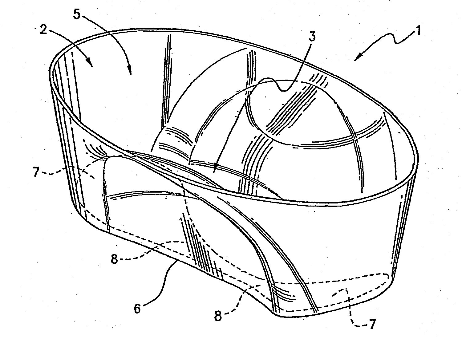
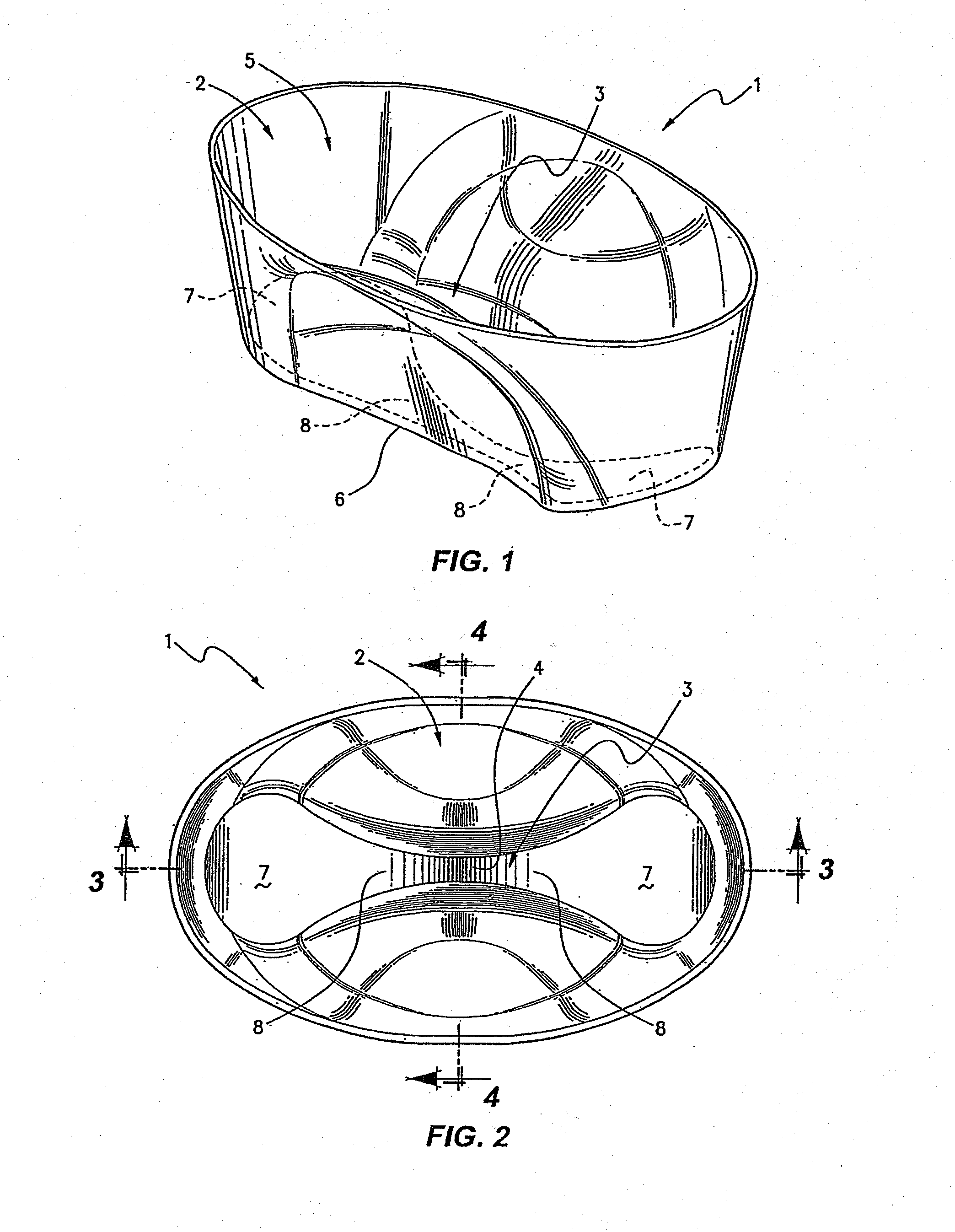
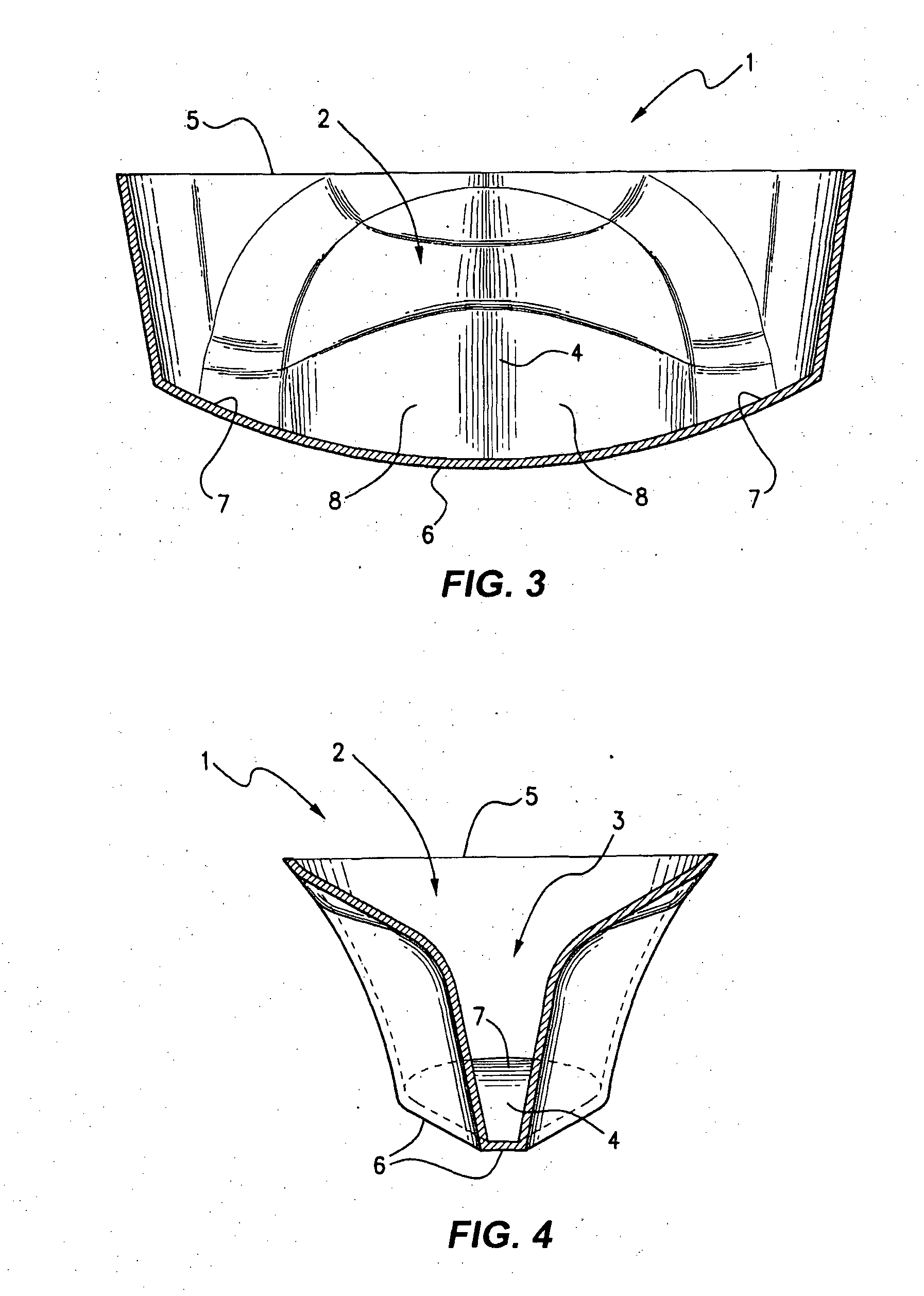
An apparatus for micromanipulation of biological material, includes a vessel (1) having a reservoir (2) wherein the vessel has a channel (3) formed in a portion of the reservoir, the channel including an intermediate restriction (4) dimensioned to resist passage of the biological material but allow passage of liquid treatment solutions.

Description

CROSS-REFERENCE TO RELATED APPLICATIONS[0001]The present application claims priority from U.S. Provisional Patent Application No. 61 / 349,296 the content of which is incorporated herein by reference.INTRODUCTION TO THE INVENTION[0002]This invention relates to apparatus and methods for the micromanipulation of biological materials and in particular, apparatus and methodologies for use in the cryopreservation of biological materials including human and non-human oocytes, embryos, sperm, stem cells and blastocyst.[0003]Whilst the invention has been developed and has application in a wide range of micromanipulation situations and techniques with a range of biological materials, it finds particular application for use in the cryopreservation of human oocytes, embryos, morula, sperm and stem cells by vitrification as applied during In Vitro Fertilisation (IVF) procedures and the like.BACKGROUND OF THE INVENTION[0004]The technologies involved and applied for cryopreserving of human and anim...

Claims


Application Information

Patent Timeline
IPC IPC(8): A01N1/02
CPCA01N1/0263A01N1/0284A61D19/022A01N1/0268A61B17/43A61B17/435A61D19/025A61D19/04
Inventor HENDERSON, CHESTER JOHNLEWIS, CRAIG MATTHEWROY, TAMMIE KIMVOM, EDUARDO
Owner GENEA IP HLDG PTY LTD
Learn More