Staggered horizontal well oil recovery process

a horizontal well and oil recovery technology, applied in the direction of fluid removal, earth-moving drilling, borehole/well accessories, etc., can solve the problems of thermal inefficiency in transferring heat to oil within the reservoir, and high cost of steam recovery methods

Inactive Publication Date: 2013-06-13
ARCHON TECH LTD
View PDF10 Cites 10 Cited by
  • Summary
  • Abstract
  • Description
  • Claims
  • Application Information

AI Technical Summary

Benefits of technology

[0113]The higher Oil Recovery Factors at 2.4 years and 5.0 years of the present invention (Line “X”) show the significant financial advantage of the present invention considering the earlier return on investment in the form of earlier and greater oil recovery. Also, with a lower Air / Oil ratio than the steam injection method (Example 3), the present invention (Example 1) will carry lower air compression costs. Because of the thermal inefficiency of steam processes, the Staggered Steam process is not competitive.
considering the earlier return on investment in the form of earlier and greater oil recovery. Also, with a lower Air / Oil ratio than the steam injection method (Example 3), the present invention (

Problems solved by technology

Such prior art method has the drawbacks of needing to provide large and costly steam-generating equipment at surface, and as noted below is thermally inefficient in transferring heat to oil within the reservoir in order to achieve the necessary reduction in viscosity to be able to produce oil from a viscous oil reservoir.
Thus substantial costs are further incurred in steam recovery methods which use steam to heat oil in heating the large quantities of steam needed, over and above the captical costs of acquiring, shipping, and assembling the necessary steam generating equipment in the form of boilers, burners, and associated piping.
Accordingly, such prior art in situ combustion recovery method does not allow production of oil from within the underground formation simultaneously along an entire horizontal length of a production well.

Method used


Image

  • Staggered horizontal well oil recovery process
  • Staggered horizontal well oil recovery process
  • Staggered horizontal well oil recovery process

Examples


example 1

Staggered Well (Air Injection) Method

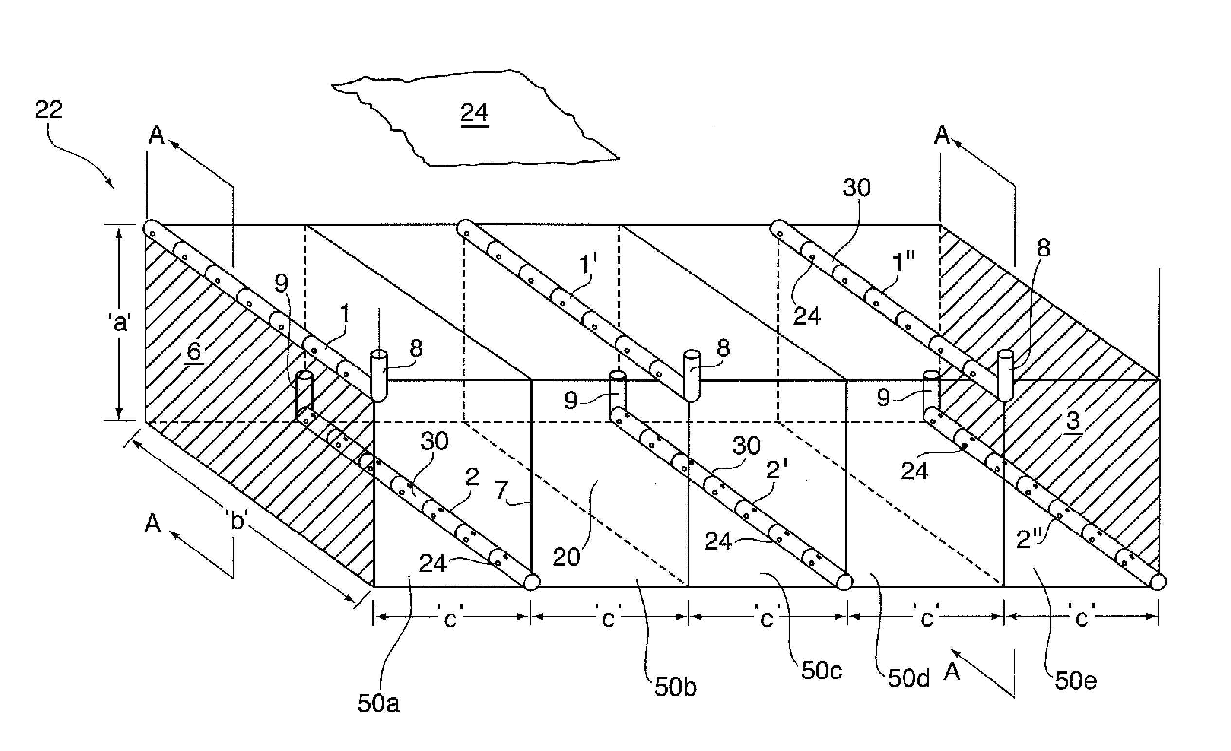
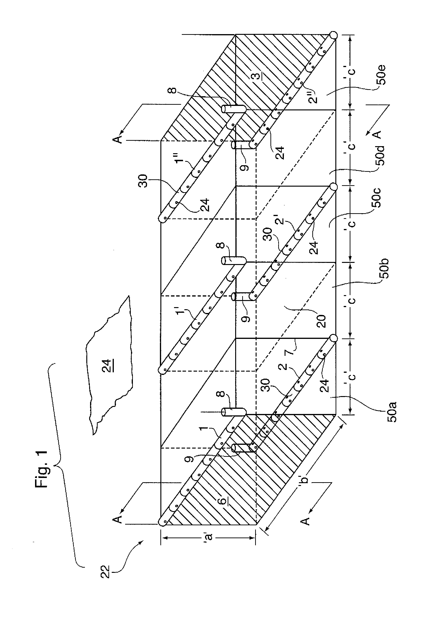
[0101]FIGS. 1 and 4(i)-(iii) depict a method of oil recovery (using air injection and in situ combustion heating) of the present invention, and in particular depict the method used in Example 1 [Staggered Well (Air Injection)], utilizing a total air injection volume of 50,000 m3 / d.

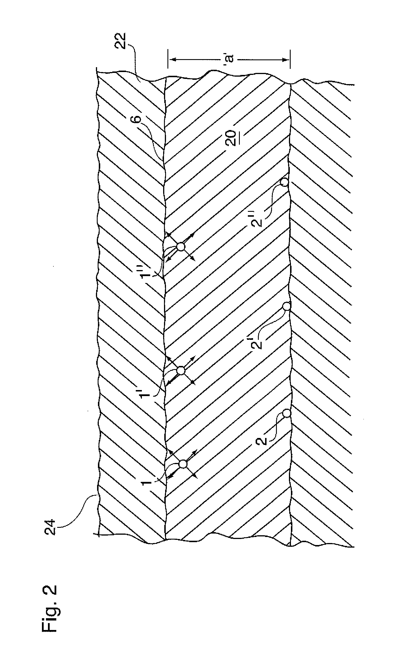
[0102]For the Staggered Well (Air Injection) Method as shown in FIGS. 1, 2.5 injection wells 1, 1′, and 1″, and 2.5 production wells 2, 2′, and 2′ as part of grid blocks 50a-50e, were all simultaneously drilled, for a total of five wells. The reservoir thickness ‘a’ was 20 m and the well offset ‘c’ was 50 m for each grid block 50a-50o. Air injection rates were 10,000 m3 / d for well 1 and 20,000 m3 / d for each of injectors 1′ and 1″, for a total of 50,000 m3 / d for the grid block pattern 50a-50e.

[0103]A summary of results, namely the Oil Recovery Factor over time (1,825 days=5 years) for Example 1, is shown in FIG. 11 as line ‘X’.

example 2

Crossed-Wells Method

[0104]FIG. 10 shows an alternative method of oil recovery from a subterranean reservoir 22, which is not the subject matter of this application but of another patent application of the within inventor and commonly assigned (hereinafter the “crossed wells” method).

[0105]In the crossed-well method depicted in FIG. 10, injector wells 1, 1′ are perpendicularly disposed to the horizontal collection wells 2, 2′, 2″, and 2′″. Specifically in this crossed-well method, parallel horizontal well injection wells 1, 1′ are placed high in reservoir 22, and parallel horizontal production wells 2, 2′, 2″, &2″ are placed low in reservoir 22 perpendicular to injection wells 1, 1′. Horizontal Injection well 1′ is located distance ‘q’ (25 m) from the front edge of the model and injection well 1 is placed distance ‘q’ from the back side of reservoir 22, namely with injectors 1, 1′ separated by a distance ‘2 q’. The well length is “b”. The spacing of the horizontal production wells is...

example 3

Staggered Steam Method

[0108]Example 3 (method of FIG. 1, but with hot steam injection instead of air injection and not employing in situ combustion) is not part of the present invention, and is only provided to illustrate the comparative efficiency with other oil recovery methods (e.g. Example 1 and Example 2).

[0109]Saturated steam was injected continuously at the rate of 150, 300 and 300 m3 / d (water equivalent—for a total of 50,000 m3 / d gaseous equivalent) into injection wells 1, 1′ and 1″ respectively, while production wells 2, 2′ and 2″ were open to production.

[0110]A summary of results of the Staggered Steam method, showing the Oil Recovery Factor over time (1,825 days=5 years) for Example 3, is shown in FIG. 11 as line ‘Y’.


PUM


Abstract

An in situ combustion process entailing the simultaneous production of oil and combustion gases that combines fluid drive, gravity phase segregation and gravity drainage to produce hydrocarbons from a subterranean oil-bearing formation, comprising initially injecting a gas through a pair of horizontal wells placed high in the formation and producing combustion gas and oil through parallel and laterally offset horizontal wells that are placed low in the formation intermediate the pair of horizontal wells placed high in the formation.

Description

FIELD OF THE INVENTION[0001]The present invention relates to an oil recovery process, and more particularly to a method of recovering oil from subterranean hydrocarbon deposits using horizontal wells and in situ combustion.BACKGROUND OF THE INVENTION[0002]There are many oil recovery processes of the prior art employed for the production of oil from subterranean reservoirs. Some of these use vertical wells or combine vertical and horizontal wells. Examples of pattern processes are the inverted 7-spot well pattern that has been employed for steam, solvent and combustion-based processes using vertical wells, and the staggered horizontal well pattern of U.S. Pat. No. 5,273,111 which has been employed (but limited to) a process using steam injection.[0003]U.S. Pat. No. 5,626,191 to Toe-to-Heel Air Injection (THAI) discloses a repetitive method whereby the vertical segment of a vertical-horizontal producer well is subsequently converted to an air injection well, to assist in mobilizing oi...

Claims


Application Information

Patent Timeline
Patent Type & Authority Applications(United States)
IPC IPC(8): E21B43/24
CPCE21B43/305E21B43/243
Inventor AYASSE, CONRAD
Owner ARCHON TECH LTD
Why Eureka
Try Eureka