High-density sample support plate for automated sample aliquoting

a sample support plate and high-density technology, applied in the field of sample support plates, can solve the problems of inability to handle small volumes of liquid samples and cells prior to analysis by maldi-ms, droplet waste, and irregular distribution of analyte molecules

Active Publication Date: 2013-06-13
ETH ZZURICH +1
View PDF15 Cites 23 Cited by
  • Summary
  • Abstract
  • Description
  • Claims
  • Application Information

AI Technical Summary

Benefits of technology

[0016]In a first aspect, it is an object of the present invention to provide a sample support plate that enables a more facile application of small amounts of liquid samples to a plurality of sample recipient sites.

Problems solved by technology

This however often results in an irregular distribution of analyte molecules over a relatively large spot size.
If a sample droplet is accidentally deposited midway between two anchor areas, it will generally not find its way to the next anchor area and will be wasted.
Also with such known sample support plates, if a sample droplet hits the area midway between two sample spots, the droplet will most likely be wasted.
As will be apparent from the prior art, it is technically challenging to handle small volumes of liquid samples and suspensions of cells prior to analysis by MALDI-MS.
Similar challenges also exist in other analytical (chemical and biological) disciplines, whenever small volumes of liquid samples, including cell suspensions, are to be distributed to well-defined sample recipient sites.

Method used


Image

  • High-density sample support plate for automated sample aliquoting
  • High-density sample support plate for automated sample aliquoting
  • High-density sample support plate for automated sample aliquoting

Examples


first embodiment

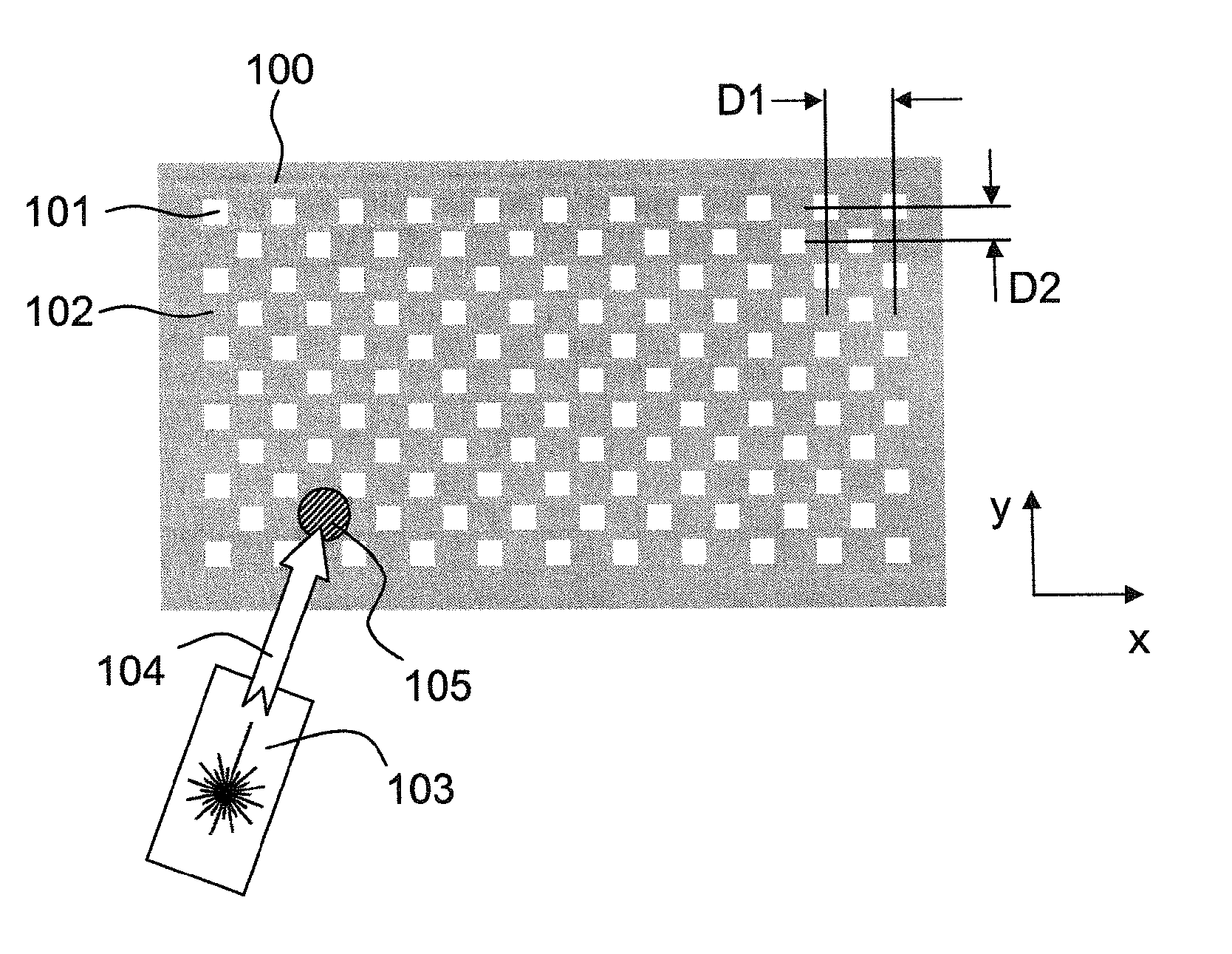
[0081]In FIG. 1, a sample support plate according to the present invention is schematically illustrated. The sample support plate comprises a stainless steel substrate 100 having a flat, planar surface coated with an omniphobic polysilazane coating. A regular arrangement of a plurality of hydrophilic sample recipient sites 101 has been produced on the substrate by removing the coating at the sample recipient sites by laser ablation, exposing the stainless steel surface at these sites, while the areas 102 between sample recipient sites remain omniphobic. The sample recipient sites have a square shape. They are arranged in a plurality of rows, wherein the recipient sites within each row are spaced along a first direction (the x direction) by a center-to-center distance or periodicity D1. Adjacent rows are shifted with respect to each other along the x direction by half the distance D1. The rows are regularly spaced along a perpendicular second direction (the y direction) by a centerli...

third embodiment

[0085]a sample support plate according to the present invention is schematically illustrated in FIG. 3. Here, the rows of sample recipient sites 101 (direction x) are inclined relative to the borders of the array of sites and to the edges of the sample support plate by an angle that is different from 0 or 90° (here approximately 27° relative to the longitudinal edge, whose direction is designated by x′). This orientation of the rows ensures that any straight line that is drawn parallel to the longitudinal edges of the sample support plate at any arbitrary position within the array will cut at least three sample recipient sites. Of course, the exact number of sample recipient sites that will be cut by the straight lines will depend on various factors, such as the number of recipient sites in the array, the shape and size of the array, size of the recipient sites, their distance along the x direction, the row spacing along the y direction, the amount of shift along the x direction bet...

fourth embodiment

[0086]FIG. 4 provides a sample support plate according to the present invention, for which a different spacing of rows and a different tilt angle between the x and x′ directions has been chosen.

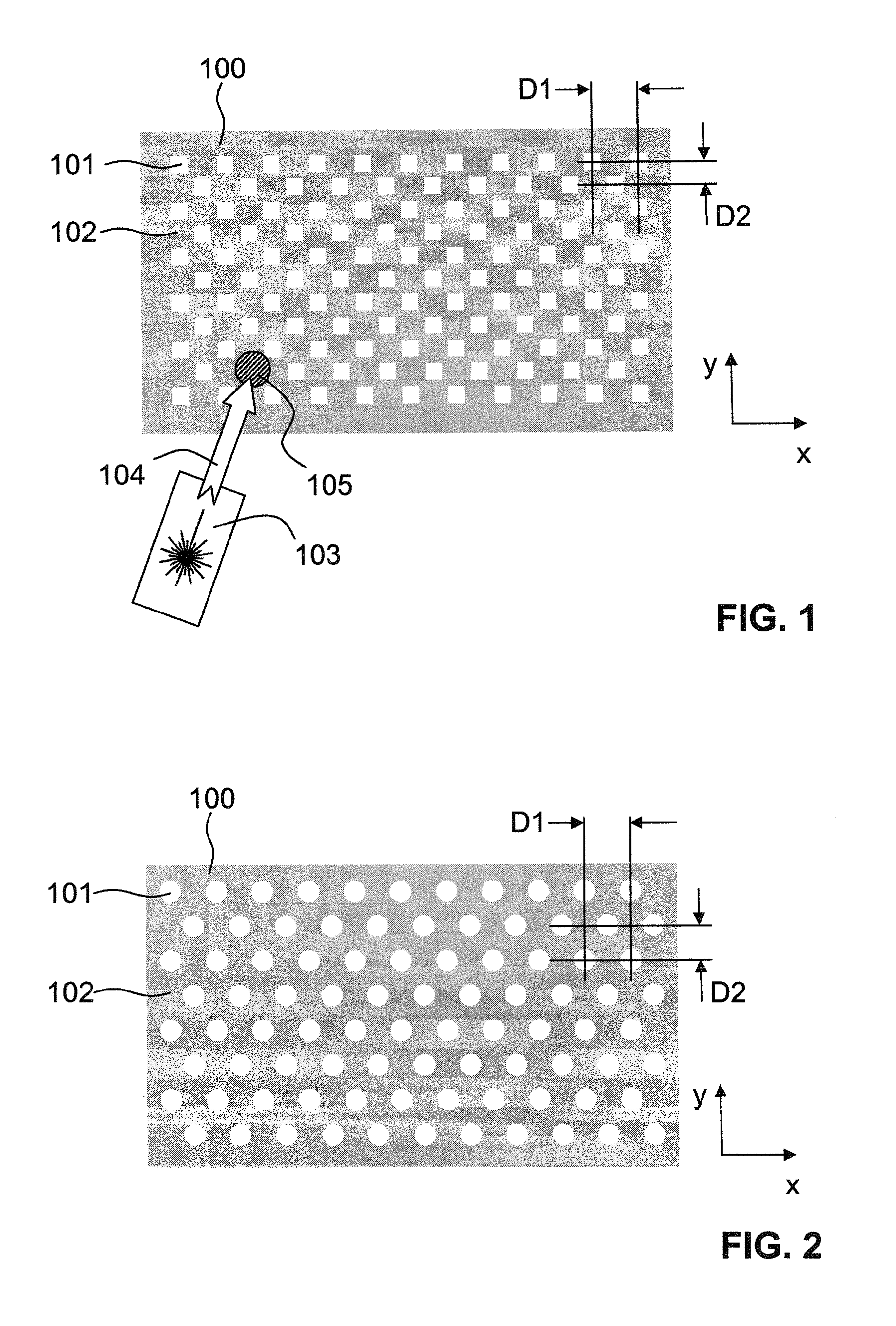
[0087]Whereas the sample recipient sites of the above examples are of square and circular shape, respectively, other shapes are possible, including elliptic, rectangular, triangular, and regular polygonal and irregular polygonal shapes.

[0088]FIG. 5(a) illustrates a first example of how a sample may be applied to a sample support plate according to the present invention. A bulk aqueous liquid, in the present example a cell suspension comprising cells 151 that are to be investigated, is spread onto a sample support plate 100 with the aid of a spreading device in the form of a glass slide 154. To this end, the glass slide is moved over the sample support plate 100 along the x direction (arrow 155). During the spreading of the liquid, liquid droplets 153 accumulate at the hydrophilic sample recip...


PUM


Abstract

A sample support plate (100) for a variety of possible applications, including MALDI mass spectrometry, is disclosed. A plurality of spatially separated sample recipient sites (101) are arranged on the surface of a substrate. The recipient sites are mutually separated by areas having a different wettability than the recipient sites. They are arranged in a plurality of rows consisting of a plurality of recipient sites whose centers are regularly spaced along a first direction with a predetermined periodicity (D1), the rows being regularly spaced along a second direction perpendicular to the first direction with a predetermined centerline distance (D2). Each recipient site has a maximum lateral dimension that is preferably smaller than the diameter of a beam spot (104) of a desorption laser beam (103). In order to enable unsupervised splitting of bulk liquid samples into droplets at the sample recipient sites, the periodicity along the first direction and the centerline distance along the second direction are chosen such that each recipient sites has a next neighbor at a distance that is less than or equal to three times the minimum lateral dimension of each recipient site. In preferred embodiments, the sample recipient sites are arranged in a checkerboard-type pattern or in rows that are inclined relative to the edges of the sample support plate.

Description

TECHNICAL FIELD[0001]The present invention relates to sample support plates having a high density of sample recipient sites, and to methods of manufacturing and using such sample support plates. Such sample support plates may be employed in a variety of applications, including but not limited to MALDI mass spectrometry, emulsion PCR, singularization of cells for various analytical applications, microcrystallization of proteins etc.PRIOR ART[0002]For the analysis of analytes containing large molecules, in particular, biomolecules, mass spectrometry using matrix-assisted laser desorption and ionization (MALDI) has become a widely used standard method. In such methods, the analyte is dispersed in a crystalline organic matrix deposited on a sample support or on the boundary surface of such a matrix. The analyte is desorbed from the sample support and ionized by action of a desorption laser beam.[0003]Various methods are known for applying the analyte and matrix to a sample support. In t...

Claims


Application Information

Patent Timeline
Patent Type & Authority Applications(United States)
IPC IPC(8): B01L9/00B05D3/00H01J49/26
CPCH01J49/0418H01J49/161H01J49/26B05D3/007B01L9/00
Inventor URBAN, PAWELZENOBI, RENATOJEFIMOVS, KONSTANTINSAMANTONICO, ANDREAFAGERER, STEPHANGOEDECKE, NILS
Owner ETH ZZURICH
Why Eureka
Try Eureka