Method and apparatus for decreasing fuel comsumption during particulate filter generation

a technology of particulate filter and fuel comsumption, which is applied in the direction of electrical control, electrical control, separation processes, etc., can solve the problems of increasing regeneration times, reducing the amount of space available in the exhaust system, and increasing the regeneration time, so as to reduce the size and reduce the amount of soot loading in the particulate filter. , the effect of accurately controlling the amount of soot loading

Inactive Publication Date: 2013-06-20
DOW GLOBAL TECH LLC
View PDF7 Cites 15 Cited by
  • Summary
  • Abstract
  • Description
  • Claims
  • Application Information

AI Technical Summary

Benefits of technology

[0011]In one embodiment, the present invention provides a diesel particulate filtration system that has a reduced size and solves one or more of the problems discussed herein. The present invention provides a diesel particulate filter system where the amount of soot loading in the particulate filter may be accurately calculated. A more accurate soot load of the diesel particulate filter allows the system to regenerate at the optimum time and allows the temperature to be more accurately controlled so that the temperature of the diesel particulate filter during regeneration can be increased, the time of the regeneration cycle can be reduced, the efficiency of the regeneration can be increased, or a combination thereof.
[0012]The present invention seeks to reduce fuel consumption by controlling process parameters during the regeneration cycles. The present invention may be used with any combustion engine. The present invention as discussed herein may be used with a gasoline engine. Particularly, the present invention may be used with a diesel engine. The present invention as discussed herein may be used with any filter that has a substantially linear relationship between soot loading and pressure drop of the particulate filter. For example, by monitoring the pressure drop across the diesel particulate filter the amount of soot loading in the diesel particulate filter can be accurately calculated. The system of the present invention can increase the temperature of the diesel particulate filter during the regeneration cycle while reducing the chances of an uncontrolled reaction (i.e., runaway reaction) because the soot load of the diesel particulate filter is accurately measured. In increasing the regeneration temperature each regeneration cycle can be performed more quickly, the efficiency of the regeneration cycle can be increased, the overall fuel consumption required to perform regeneration cycles over the life of the diesel particulate filter can be reduced, or a combination thereof.
[0013]In another embodiment of the present invention the size (i.e. the length, diameter, cross sectional area, or a combination thereof) of the diesel particulate filter may be reduced without sacrificing performance or unnecessarily increasing the number of regeneration cycles needed to be performed. A reduction in the size of the diesel particulate filter may provide space in the exhaust system for the inclusion of other emission components, without reducing the efficiency of the diesel particulate filter, without reducing the efficiency of the exhaust system, reducing the system cost of the exhaust system, or a combination thereof. An optimum diesel particulate filter size may be calculated by measuring the pressure drop across the diesel particulate filter and using look-up tables so that the amount of fuel consumed during a regeneration cycle is decreased.
[0014]In yet another embodiment of the present invention the control system may regulate engine speed, exhaust gas recirculation, the throttle valve opening, or a combination thereof so that the temperature of the particulate filter may be controlled during a regeneration cycle when the engine speed is reduced to an idle. The present invention increases or maintains air flow through the diesel particulate filter when the engine speed is reduced to an idle such that heat is removed from the particulate filter and the peak outlet temperature is reduced so that the particulate filter is not damaged. Air flow and / or space velocity of exhaust may be controlled by either opening the throttle valve or maintaining the throttle valve in the open position when the engine speed is reduced. Air flow and / or space velocity of exhaust may further be increased by reducing or eliminating the amount of exhaust gas recirculation. The present invention is able to reduce the temperature of the particulate filter, to below temperatures that may damage the particulate filter, by increasing the throttle valve opening and / or decreasing exhaust gas recirculation for about two minutes or less when the regeneration cycle has progressed for five or less minutes before the speed of the engine is reduced to an idle.

Problems solved by technology

The addition of one or more of these components has reduced the amount of space available in the exhaust system.
Regeneration of the particulate filters is performed when the particulate filters reach a target soot loading and / or it becomes increasingly difficult for the exhaust to pass through the particulate filter.
Currently, there is no accurate way to calculate the actual soot load (i.e., target soot load) of a particulate filter; thus, regeneration cycles are triggered based upon fuel consumption, vehicle mileage, engine running time, and engine emission rates.
Thus, due to the variability in calculating the target soot load of the particulate filters the inlet gas temperature may be set for the maximum soot load, which may result in increased regeneration times, higher or lower temperatures than the target temperatures, inconsistent efficiency from regeneration to regeneration, low regeneration efficiency, the regeneration cycle occurring below and / or above the target soot load, or a combination thereof.
Temperatures greater than about 1000° C. may cause the particulate filter to crack, melt, deactivate or reduce the efficiency of a catalyst coating on the particulate filter, or a combination thereof.
If the particulate filter cracks, melts, or the catalyst coating is deactivated compliance with environmental regulations (e.g. regulations by the Environmental Protection Agency (EPA)) may not be met.
However, maintaining the engine at a higher speed during idle presents other challenges such as engine noise, emissions, and may also result in a fuel penalty.

Method used


Image

  • Method and apparatus for decreasing fuel comsumption during particulate filter generation
  • Method and apparatus for decreasing fuel comsumption during particulate filter generation
  • Method and apparatus for decreasing fuel comsumption during particulate filter generation

Examples


Embodiment Construction

[0031]The following description of the preferred embodiment(s) is merely exemplary in nature and is in no way intended to limit the invention, its application, or uses.

[0032]The present invention is predicated upon providing an improved diesel particulate filter, an improved system for regeneration of a diesel particulate filter, and an improved method for designing a diesel particulate filter for a system. The present invention further regulates the engine so that when the engine speed is reduced to an idle while a regeneration cycle is in progress the temperature of the particulate filter is controlled and the particulate filter is not damaged.

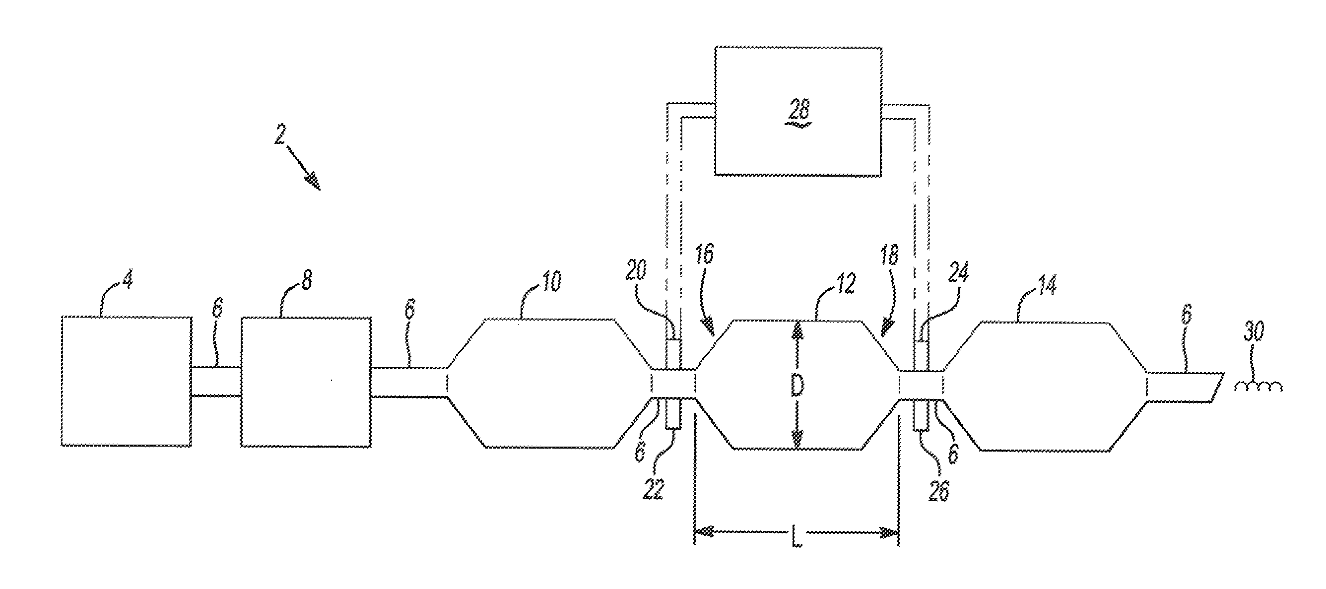
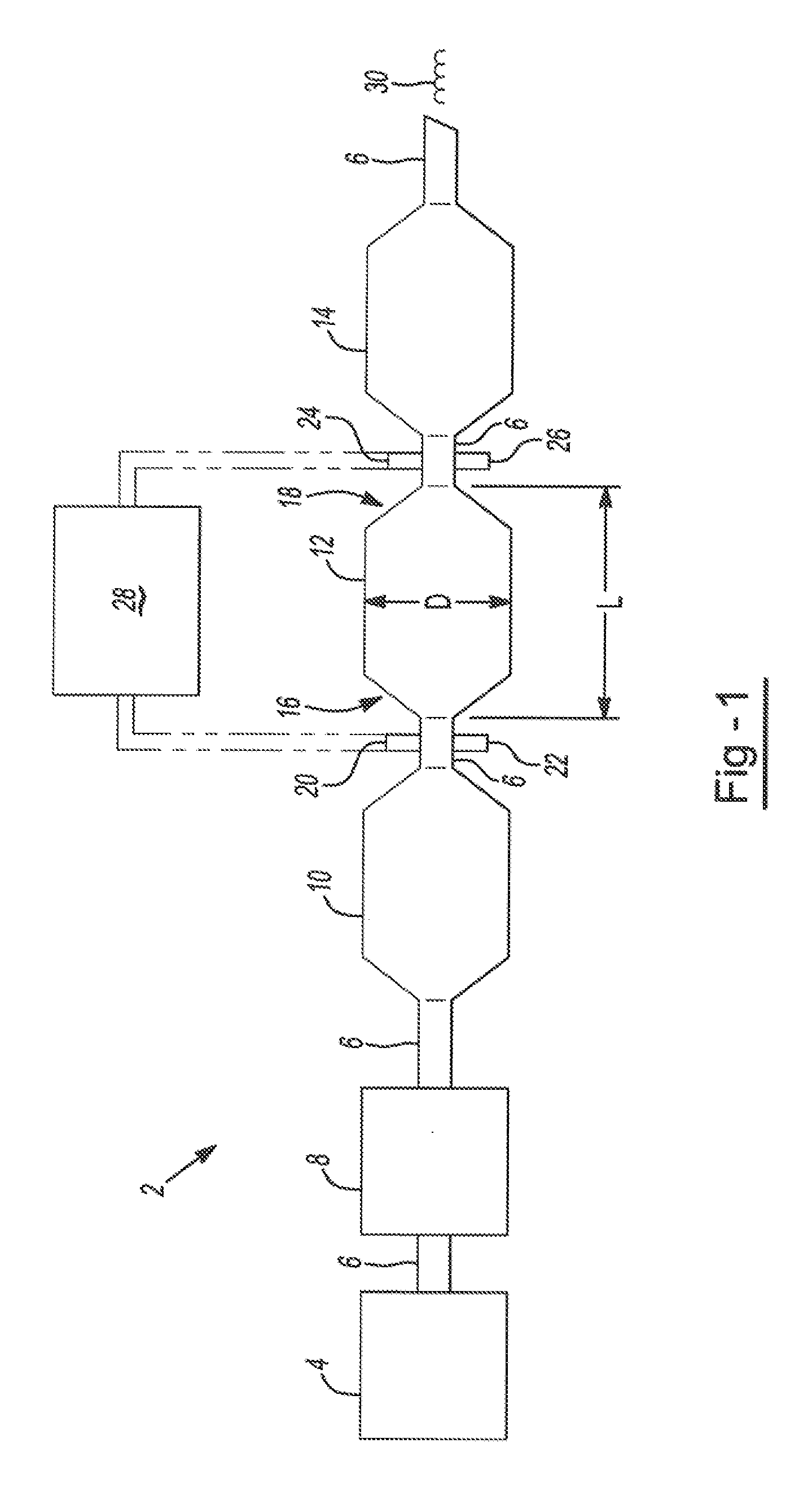
[0033]An exhaust system includes a particulate filter. The particulate filter may be made of any material suitable that removes soot from an exhaust stream, and particularly from a diesel engine exhaust stream. Preferably, the diesel particulate filter may be made of any material that exhibits substantially linear characteristics that corres...


PUM

PropertyMeasurementUnit
temperatureaaaaaaaaaa

Abstract

A diesel particulate filter system comprising: a temperature sensor on the inlet side of the diesel particulate filter; a temperature sensor on the outlet side of the diesel particulate filter; a pressure sensor on the inlet side of the diesel particulate filter; and a control module in communication with the temperature sensors and the pressure sensor, and the control module is loaded with a look-up table that correlates the amount of soot loaded in the diesel particulate filter to a change in pressure measured by the pressure sensor; wherein the control module Initiates a regeneration cycle when soot loading of the diesel particulate filter achieves a predetermined soot load.

Description

CLAIM OF PRIORITY[0001]The present teachings are related to U.S. Provisional Application Ser. No. 61 / 381,290 filed Sep. 9, 2010, the contents of which are incorporated by reference herein.FIELD OF THE INVENTION[0002]The present invention generally relates to a system that includes a particulate filter to control emissions, and more specifically a process for optimizing a regeneration cycle of a particulate filter, calculating the optimum size of a particulate filter, and controlling the particulate filter temperature when the engine speed is reduced to an idle.BACKGROUND OF THE INVENTION[0003]Typical engines have an exhaust system that include a filtration process for filtering particulates out of the exhaust stream so that the emissions exiting the exhaust system comply with regional environmental regulations and / or worldwide environmental regulations. These environmental standards and regulations are becoming stricter and require that the amount of Nitrogen Oxide (NOx), Hydrocarbo...

Claims


Application Information

Patent Timeline
Patent Type & Authority Applications(United States)
IPC IPC(8): F01N3/023F01N3/021
CPCF01N3/035F01N3/106F01N3/2066F02D41/1446F02D2200/0812F01N3/021F01N3/023F02D41/029Y02A50/20F01N9/00F02D41/02
Inventor KOTNISH, ASHISH
Owner DOW GLOBAL TECH LLC
Why Eureka
Try Eureka