Pathology Slide Scanner

a slide scanner and pathology technology, applied in the field of microscope imaging of large specimens, can solve the problems of increasing the chance of tiling artifacts, increasing bleaching, and slow fluorescence imaging of tiling microscopes, and achieve the effect of expanding the dynamic rang

Active Publication Date: 2013-06-20
HURON TECH INT
View PDF7 Cites 53 Cited by
  • Summary
  • Abstract
  • Description
  • Claims
  • Application Information

AI Technical Summary

Benefits of technology

[0021]“Proper exposure” is defined as a gain setting such that in the output image file, no (or only a small number of) pixels are saturated, and the dynamic range of the image data matches the dynamic range of the output image file (8 bits for an 8 bit file, 12 bits for a 12 bit file, etc.) and includes substantially the entire range of pixel amplitudes from the noise floor to the brightest pixel. The output image file may have a smaller dynamic range than that of the detection system, and that of an intermediate image file that is collected during scanning. WO2009 / 137935 describes two methods of maximizing the dynamic range of data stored in the output image file—(1) accurately estimating the gain required to maximize the dynamic range of each detection channel when the dynamic range of the detection channel and the dynamic range of the output image data file are the same, and (2) using a dynamic range in the detection channel that is larger than that required in the final image data file and contracting the acquired data to utilize substantially the entire dynamic range of the final image data file.
[0026]It is an object of this invention to provide an imaging system for large microscope specimens using one or more CCD or CMOS or other technology two-dimensional sensor arrays whereby noise in the image is reduced by adding together a sequence of overlapping images on a line-by-line basis, whereby each line of the final image is the result of adding several exposures of the same line, thus increasing the exposure time for that line in the image.

Problems solved by technology

Such images may contain tiling artifacts, caused by focus changes between adjacent tiles, differences in illumination intensity across the field of view of the microscope, barrel or pincushion distortion near the edge of the tiles, and microscope objectives that do not have a flat focal plane.
For large specimens, thousands of tiles may be required to image the entire specimen, increasing the chance of tiling artifacts.
Tiling microscopes are very slow for fluorescence imaging as one image is taken of each tile
Multiple exposure of the specimen for imaging multiple fluorophores can also increase bleaching.
Stitching tiles together is also complicated by distortion and curvature of field of the microscope objective, which occur near the edges of the field of view (just where stitching of tiles occurs).
Varying exposure by changing scan speed makes it difficult to design a strip-scanner for simultaneous imaging of multiple fluorophores, where each channel would have the same exposure time, and present strip-scanners scan one fluorophore at a time.
For strip-scanning instruments, estimating the exposure in advance is difficult without scanning the whole specimen first to check exposure, and this must be done for each fluorophore.
Instead of scanning first to set exposure, many operators simply set the scan speed to underexpose slightly, with resulting noisy images, or possibly images with some overexposed (saturated) areas if the estimated exposure was not correct.
When a CCD-based linear TDI array is used, each line image stored in memory is the result of integrating the charge generated in all of the previous lines of the array while the scan proceeds, and thus has both increased signal / noise and amplitude (due to increased exposure time) when compared to the result from a linear array detector.
In addition, it is difficult to predict the best exposure time before scanning.
Some instruments use multiple linear TDI detector arrays to expose and scan multiple fluorophores simultaneously, but this usually results in a final image where one fluorophore is exposed correctly and the others are either under- or over-exposed.
Linear arrays are not often used for fluorescence imaging because exposure time is inversely proportional to scan speed, which makes the scan time very long for weak fluorophores.
In addition, exposure (scan speed) must be adjusted for each fluorophore, making simultaneous measurement of multiple fluorophores difficult when they have widely different fluorescence intensity (which is common).
Linear TDI arrays and associated electronics are expensive, but the on-chip integration of several exposures of the same line on the specimen provides the increased exposure time required for fluorescence imaging while maintaining a reasonable scan speed.
Simultaneous imaging of multiple fluorophores using multiple linear TDI detector arrays is still very difficult however, since each of the linear detectors has the same integration time (set by the scan speed), so it is common to use only one linear TDI array, adjusting exposure for each fluorophore by changing the scan speed and collecting a separate image for each fluorophore.

Method used


Image

  • Pathology Slide Scanner
  • Pathology Slide Scanner
  • Pathology Slide Scanner

Examples


first embodiment

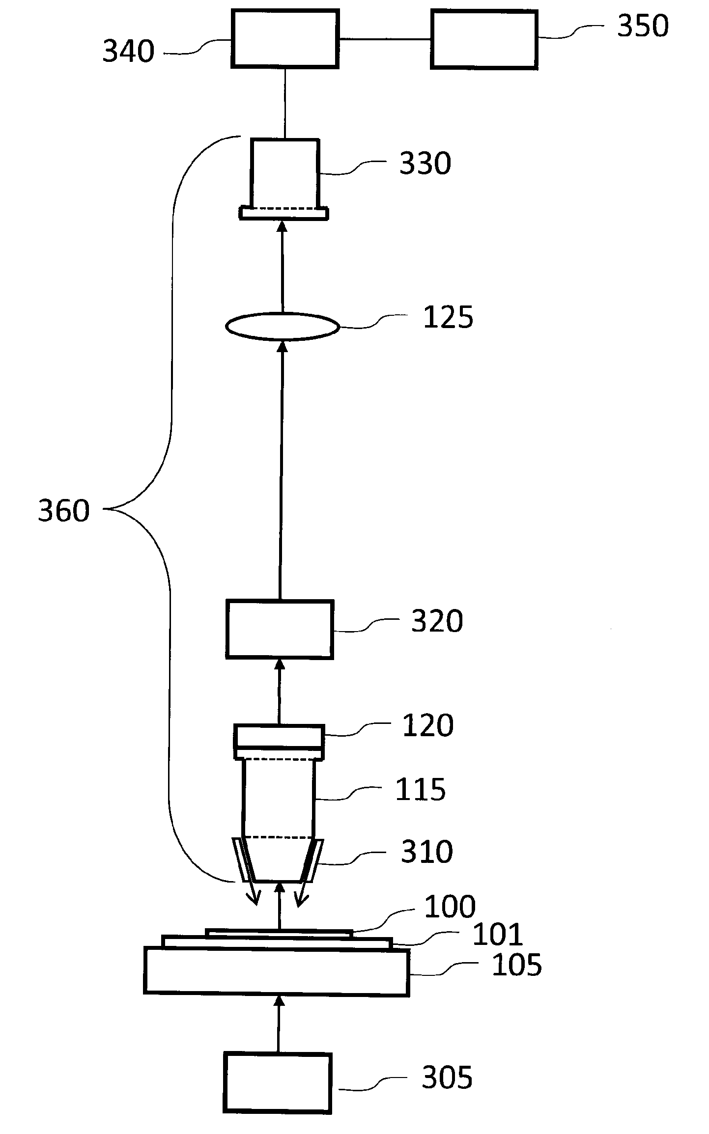
[0059]FIG. 3 shows a microscope for fluorescence and brightfield imaging that is this invention. A tissue specimen 100 (or other specimen to be imaged) mounted on microscope slide 101 on a scanning stage 105. When used for fluorescence imaging, the tissue specimen is illuminated from above by illumination source 310, mounted above the specimen (epifluorescence) so that the intense illumination light that passes through the specimen is not mixed with the weaker fluorescence emission from the specimen, as it would be if the fluorescence illumination source were below the specimen. Several different optical combinations can be used for epifluorescence illumination—light from a source mounted on the microscope objective, as shown; illumination light that is injected into the microscope tube between the microscope objective and the tube lens, imaged onto the back aperture of the objective, using a dichroic beamsplitter to reflect it down through the microscope objective and onto the spec...


PUM


Abstract

An instrument and method for scanning at least a portion of a large specimen preferably causes the specimen to move relative to a two-dimensional detector array at a constant speed. The detector array takes one image of the specimen for each line that the detector moves. A controller controls a shutter of the detector array to open to take images and to pass the images to a processor, which is preferably a computer. The instrument takes one partial image of each part of the specimen that is being scanned and then combines those images with other images to produce a contiguous image.

Description

BACKGROUND OF THE INVENTION[0001]1. Field of the Invention[0002]This invention relates to the field of microscopic imaging of large specimens with particular emphasis on brightfield and fluorescence imaging, including photoluminescence and spectrally-resolved fluorescence. Applications include imaging tissue specimens, genetic microarrays, protein arrays, tissue arrays, cells and cell populations, biochips, arrays of biomolecules, detection of nanoparticles, photoluminescence imaging of semiconductor materials and devices, and many others.[0003]2. Description of the Prior Art[0004]The macroscope originally described in U.S. Pat. No. 5,381,224 is a scanning-laser system that uses a telecentric laser-scan lens to provide a wide field of view. Several embodiments are presently in use. These include instruments for fluorescence and photoluminescence (including spectrally-resolved) imaging (several other contrast mechanisms are also possible), instruments in which a raster scan is provid...

Claims


Application Information

Patent Timeline
Patent Type & Authority Applications(United States)
IPC IPC(8): G02B21/06
CPCG02B21/002G02B21/06G02B21/367
Inventor DIXON, ARTHUR EDWARD
Owner HURON TECH INT
Why Eureka
Try Eureka